
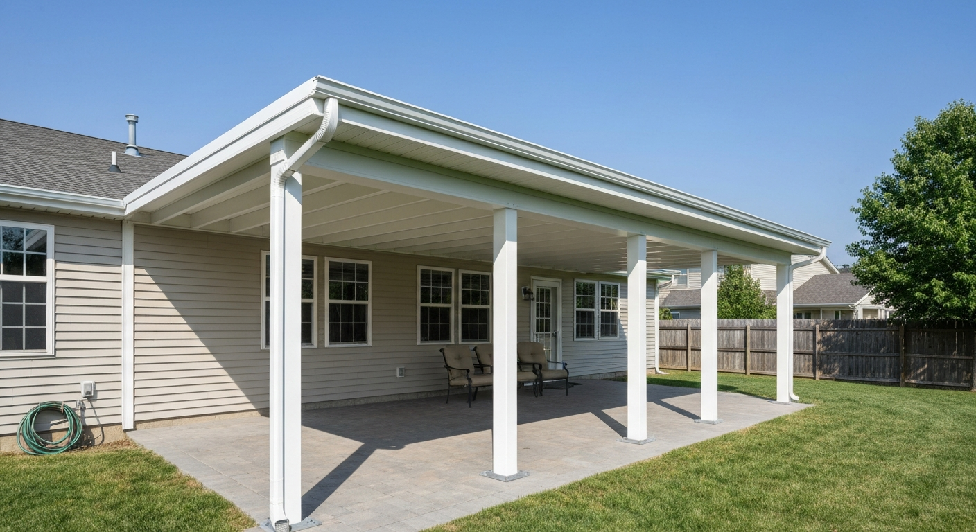
You can build a vinyl patio cover yourself in a long weekend if you pick a manufactured kit system, have basic carpentry skills, and sort out your permit first. LedgerLOK (FastenMaster) product/technical information and ICC‑ES listing notes that Manufacturers of ICC‑ES‑listed ledger screws (FastenMaster LedgerLOK, Simpson SDWS/Strong‑Drive) publish spacing and load tables for ledger connections; use the manufacturer spacing/load tables or an ICC‑ES evaluation report rather than generic deck screws. A standard attached lean-to vinyl cover over a 12x16-foot patio runs roughly $1,800 to $4,500 in materials depending on the kit brand and any upgrades, and most homeowners with mid-level DIY experience can complete it in two to three days once the footings have cured. The trickier variables are not the vinyl itself but the structural decisions underneath it: footing depth, ledger attachment to your house, beam and rafter sizing, and making sure the whole thing meets your local building code.
How to Build a Vinyl Patio Cover: Plan, Build & Install

What this guide covers and who it is for
This guide walks you through every stage of planning and building an attached lean-to vinyl patio cover, from the first tape-measure pass to the final trim piece. Along the way it covers the structural principles that apply to gable and free-standing vinyl covers too, so you can adapt the instructions as needed. If you are also weighing cedar, lattice, or cantilever designs, those share many of the same foundation and ledger rules covered here. For step-by-step instructions on a different approach, see how to build a cantilever patio cover. The guide is aimed at homeowners who are comfortable using power tools, following a manufacturer's manual, and making a permit application, but who are not structural engineers. Where the work crosses into engineering territory, I flag it clearly.
Make these decisions before you buy anything
Rushing to the lumber yard before answering a handful of planning questions is the single most common reason patio cover projects stall or get torn down. Work through this checklist first.
- Roof style: lean-to (attached, single slope) is the simplest and least expensive; gable (peaked, attached or free-standing) adds cost and framing complexity; free-standing requires all four sides to carry loads independently; cantilever eliminates a front post line but demands careful beam and footing engineering.
- Material: vinyl kit systems arrive pre-engineered with load ratings and installation manuals, which simplifies permitting; custom-framed vinyl-clad structures use dimensional lumber or steel framing covered with vinyl components, and require member sizing from span tables or an engineer.
- Span and post spacing: most vinyl kit manufacturers publish maximum allowable spans (commonly 12 to 20 feet for rafters, 8 to 12 feet for post spacing); do not exceed these numbers without site-specific engineering.
- Load considerations: confirm your local ground snow load and basic wind speed from IRC Table R301.2(1) or ASCE 7-22 hazard maps — then check that the kit's published load ratings meet or exceed those values.
- Attachment method: attached covers connect to the house via a ledger; the ledger must be bolted through the rim joist or wall framing, not just screwed to siding; free-standing covers avoid ledger issues entirely but need heavier footings.
- Budget: expect $1,800 to $2,800 for a basic 12x16 vinyl kit plus hardware; $3,000 to $4,500 with upgraded panels, gutters, and ceiling options; add $500 to $1,200 for permit fees, concrete, and post anchors depending on your location.
Permits, codes, setbacks, and inspections
Pull the permit. I know it sounds tedious but a patio cover attached to a house is a structure, and most jurisdictions require a building permit for any attached shade structure over roughly 200 square feet, and many require one for smaller structures too. Unpermitted covers can complicate home sales, void homeowner's insurance claims, and in worst cases get ordered removed. The permitting process also forces you to document your design, which catches structural errors before you pour concrete.
Your local Authority Having Jurisdiction (AHJ) will use IRC Table R301.2(1) to set the design values for your site: ground snow load, basic wind speed, frost depth, seismic design category, and weathering severity. Pull up ASCE 7-22 wind and snow hazard maps online to get a rough idea of your design values before visiting the permit office. Most jurisdictions also set minimum setbacks from property lines for accessory structures, typically 5 to 10 feet on side and rear yards, but this varies widely.
- Contact your local building department and ask specifically whether a vinyl patio cover requires a permit, what drawings are needed, and whether the manufacturer's engineering documentation for a kit system is acceptable.
- Ask about setback requirements for attached versus free-standing structures.
- Confirm the local frost depth so you can size footings correctly under IRC R403.1.4.
- Ask how many inspections are required and at what stages (typically: footing before pour, framing before cover, and final).
- If you live in an HOA, check their guidelines separately — they can require approval even when the city does not.
Tools and materials you will need
Core tools for any vinyl patio cover build
- Tape measure (25-foot minimum), chalk line, and speed square
- Post-hole digger or rented power auger (for footing holes)
- Level (4-foot and torpedo), plumb bob or laser level
- Circular saw or miter saw with a fine-tooth blade (vinyl cuts cleanly with a fine-tooth or reverse-tooth blade to reduce chipping)
- Drill/driver (corded or 18V+ cordless with spare battery), impact driver
- Hammer drill and concrete drill bits (for ledger and anchor bolts into masonry or concrete)
- Socket wrench set and adjustable wrench
- Safety glasses, work gloves, hearing protection, hard hat for overhead work
- Scaffolding or pump-jack system for roof-level work (do not rely on ladders for sustained overhead framing)
Materials for a lean-to vinyl kit cover (12x16 example)
- Manufactured vinyl patio cover kit (beam, rafters, posts, panels, and trim — sized per manufacturer's span tables)
- Post base anchors (Simpson ABA or equivalent, with ICC-ES listing) and J-bolts or anchor bolts set in concrete
- Ledger board (typically 2x8 or 2x10 dimensional lumber or the kit's aluminum/vinyl ledger channel) and LedgerLOK or SDWS structural screws at manufacturer-specified spacing
- Self-adhesive flashing tape and step flashing or z-flashing for ledger-to-wall junction
- Concrete (minimum 3,000 psi for footings per IRC R403 and most local amendments)
- Tube forms (Sonotube or equivalent) sized to footing diameter required by engineering or local minimum
- Hot-dip galvanized or stainless steel hardware throughout — do not use zinc-plated screws near treated lumber or vinyl; follow Simpson's corrosion class guidelines
- Silicone or vinyl-compatible caulk for panel joints and trim
Optional upgrades worth considering
- Insulated vinyl roof panels (improve thermal comfort and reduce condensation drip)
- Integrated gutters and downspouts (most kit manufacturers offer these as bolt-on add-ons)
- Ceiling panel systems (tongue-and-groove vinyl plank gives a finished soffit look)
- Polycarbonate panels in place of opaque vinyl panels (adds natural light; check manufacturer compatibility)
- Electrical rough-in conduit (install before panels go on — much harder to add later)
Structural basics: loads, spans, and sizing
Vinyl patio cover kits are pre-engineered, meaning the manufacturer has already calculated whether the extrusions and connectors can carry a specified combination of dead load (the weight of the cover itself), live load (maintenance workers, snow accumulation), and wind uplift. That engineering is only valid if you stay within the published limits. When you go off-script, longer spans, heavier snow load, higher wind zone, you need a licensed structural engineer to produce stamped calculations.
For custom-framed vinyl-clad covers (lumber frame with vinyl cladding), you size members the same way you would a deck or light framing project. The American Wood Council's span tables give allowable spans and cantilever limits for dimensional lumber by species and grade. The prescriptive cantilever limit for joists is generally the lesser of the tabulated overhang length or one-quarter of the back span (L/4). Always look up the actual table for your lumber species and size rather than guessing, the difference between a 2x8 and a 2x10 Southern Yellow Pine rafter can mean several additional feet of allowable span.
Beams carrying posts must transfer loads to footings without exceeding bearing capacity. For most residential soils, an 18-inch diameter footing at the correct depth handles typical residential patio loads, but expansive clay or very soft soils may require larger footings or soil testing. When in doubt, a brief consultation with a structural engineer or your building department is far cheaper than a footing failure.
| Structural Element | Common Prescriptive Rule | Where to Verify |
|---|---|---|
| Rafter span | Up to ~16 ft for 2x8 SPF No.2 at 24" o.c. (load-dependent) | AWC Span Tables / manufacturer manual |
| Rafter cantilever | Lesser of tabulated LO or L/4 of back span | AWC Prescriptive Deck Guide |
| Post spacing | Typically 8–12 ft per vinyl kit; custom per beam size | Manufacturer manual or engineer |
| Footing depth | Below local frost line per IRC R403.1.4 | Local AHJ / frost-depth lookup tool |
| Footing concrete strength | Minimum 2,500–3,000 psi; many jurisdictions require 3,000 psi | Local code / IRC R403 |
| Ledger fasteners | LedgerLOK or SDWS at spacing per ICC-ES ESR table | Manufacturer load table / ESR report |
Site prep: measuring, layout, footings, and soil
Before you dig a single hole, establish your layout precisely. A 3-4-5 triangle (or its multiples like 6-8-10) is your best friend for squaring the post layout to the house. Measure 3 feet along the house wall, 4 feet out from that point, and confirm the diagonal is exactly 5 feet. If it is not, your rectangle is not square, and every vinyl panel and rafter will fight you.
- Mark the house attachment line where the ledger will go. Snap a chalk line at the finished ledger height, accounting for roof slope (typically 1/4 inch per foot minimum for drainage — so a 12-foot-deep cover needs a 3-inch drop from house to outer beam).
- Measure out from the house the full cover depth and mark the post center locations with stakes and string. Confirm square using the 3-4-5 method.
- Locate utility lines before digging — call 811 (USA) or your regional equivalent at least two business days before excavation.
- Dig footing holes to the required frost depth plus 6 inches. In northern climates (Chicago, Minneapolis) this can mean 42 to 48 inches deep; in mild climates (southern coastal areas) 12 to 18 inches may be acceptable, but always confirm with your AHJ.
- Add 6 inches of compacted gravel at the base of each hole for drainage.
- Set tube forms (Sonotube) flush with or slightly above grade to keep concrete above soil contact.
- Mix or pour 3,000 psi concrete, set J-bolts or post base anchors to the exact layout while concrete is wet, and check alignment with a string line. Recheck after 24 hours before the concrete fully cures.
Common mistake: people set J-bolts slightly off position and then try to bend them into place after the concrete cures. Use a wood template cut to match your post base bolt pattern to hold anchors in exact position while the concrete sets. It takes 10 extra minutes and saves hours of frustration.
Soil type matters more than most homeowners realize. Sandy or gravelly soil drains well and provides reasonable bearing. Expansive clay can heave footings in freeze-thaw cycles. If you are in a clay-heavy region, a flared or belled footing bottom (wider at the base) resists uplift better. If the soil looks unusually soft or wet, get a quick opinion from a local structural engineer or your building department before pouring.
Ledger attachment, post anchors, and flashing
The ledger connection is where patio cover failures most often start, so this section deserves extra attention. Ledger failures typically happen for one of three reasons: fasteners installed into rim joist blocking rather than the actual rim joist, fasteners that are too small or too few, or water infiltrating behind the ledger and rotting the house's rim joist over time. All three are preventable.
Ledger fastening
Use ICC-ES-listed structural screws, FastenMaster LedgerLOK or Simpson SDWS are the most widely available. Both have published installation tables that tell you exactly how many fasteners per lineal foot you need based on joist tributary load. Do not use standard lag screws with generic spacing; the IRC prescriptive ledger connection tables (IRC R507 / R502 series depending on your edition) specify fastener size, row spacing, and row stagger. Two staggered rows of LedgerLOK at the spacing listed in the ICC-ES evaluation report (such as ESR-1663 for LedgerLOK) is the typical approach for an attached residential patio cover.
Flashing the ledger
Remove the siding behind the ledger location before installation. Install self-adhesive flashing membrane on the sheathing, then slide z-flashing or step flashing up under the course of siding above the ledger, folding it over the top edge of the ledger. The goal is a water-shedding path that directs any infiltration away from the house's structural members. Caulk alone is not adequate. What often goes wrong here is installers leave the siding in place and try to tuck flashing into the gap, this almost always fails within a few years.
Post anchor connectors
Post bases like the Simpson ABA or ABU series keep the post bottom off the concrete surface, which prevents moisture wicking and greatly extends post life. The anchors must be installed with the fasteners specified in the ICC-ES evaluation report for that product, substituting a shorter or weaker fastener voids the published load values. For anchors set into existing concrete slabs or existing masonry, use expansion anchors or epoxy anchors following the specific ESR report for that anchor; embedment depth and edge distance requirements are non-negotiable and are listed in the report.
Corrosion and fastener compatibility
If your framing uses pressure-treated lumber, standard zinc-plated hardware will corrode rapidly due to the chemicals in the wood. Use hot-dip galvanized (HDG) or stainless steel connectors and fasteners throughout, this applies to post bases, joist hangers, and every screw or bolt in contact with treated wood. Simpson's corrosion classification system (G90 galvanized vs. ZMAX vs. stainless) tells you which product to use by exposure level and treated lumber type. Vinyl itself is not reactive, but wherever vinyl panels contact aluminum or steel framing components, check manufacturer guidance on isolating dissimilar metals.
Step-by-step: building an attached lean-to vinyl patio cover
This walkthrough assumes you are installing a manufacturer's vinyl kit on a concrete patio slab adjacent to the house, with the ledger attaching to a wood-framed exterior wall. The kit provides the beam, rafter components, posts, panels, and trim. Adjust fastener details if your house wall is masonry or if you are working from scratch with a custom lumber frame clad in vinyl.
Stage 1: Final layout and ledger installation
- Confirm permit is in hand and schedule the footing inspection before you pour concrete.
- Snap a level chalk line on the house wall at the ledger height. Account for roof slope: if the cover is 12 feet deep and you want 1/4-inch-per-foot pitch, the ledger sits 3 inches higher than the outer beam height.
- Remove siding in the ledger zone. Cut siding flush to the framing layout — do not just notch around the ledger.
- Install self-adhesive flashing tape on sheathing behind the ledger location.
- Tack the ledger board (or kit ledger channel) into position and use a level to confirm it is dead level side to side.
- Drill pilot holes and drive LedgerLOK or SDWS screws in the pattern specified by the manufacturer's load table. Two offset rows with spacing per the ICC-ES ESR is standard.
- Install z-flashing above the ledger, tucking it under the lowest course of siding above. Caulk the top siding edge where it meets flashing with a high-quality exterior silicone.
- Safety check: tug the ledger hard. It should feel absolutely rigid. If it moves, add fasteners and investigate whether you are hitting solid rim joist.
Stage 2: Footing and post installation
- Dig footing holes at the post layout positions to the locally required frost depth. Call 811 before you dig.
- Set tube forms, pour 3,000 psi concrete, and set post base anchors (J-bolts or embedded bases) using your wood alignment template. Check plumb and position on all anchors before the concrete stiffens.
- Allow concrete to cure a minimum of 48 to 72 hours before loading the posts. In cold weather, tent and heat the forms for at least 24 hours and extend cure time.
- Set posts into the anchors and fasten per the ICC-ES report for the post base. Brace posts temporarily in both directions with 2x4 diagonal braces staked to the ground — posts must stay perfectly plumb until the beam is installed.
- Safety check: confirm every post is plumb on two perpendicular faces before releasing the braces for framing.
Stage 3: Beam installation
- Lift the outer beam (this is a two- or three-person job for beams over 12 feet) onto the post tops and set it into the post cap connectors.
- Confirm the beam is level end to end and at the correct height relative to the ledger for your designed roof slope.
- Fasten beam to post caps with the specified fasteners per the connector's load table.
- If the kit uses a vinyl beam wrap, slide the wrap onto the structural member now — it is nearly impossible to install later once rafters are in place.
- Common mistake: people assume the beam is the vinyl extrusion alone. Many vinyl kit systems use a hidden structural lumber or steel core inside the vinyl shell. Read the kit manual carefully to identify what carries the load.
Stage 4: Rafter installation
- Starting from one end, set each rafter into the ledger rafter channel or bird's-mouth notch at the house end, and rest the far end on the beam. Most vinyl kit rafters use a slide-and-lock mechanism into extruded channels — follow the kit sequence exactly.
- Space rafters at the on-center spacing specified in the manufacturer's manual (commonly 24 inches for vinyl panel kits).
- For custom lumber-framed covers, cut a bird's-mouth at the beam end to seat the rafter on the beam without relying purely on the fastener for vertical support.
- At the ledger end, use joist hanger hardware approved for the rafter size if not using the kit's proprietary channel system.
- Safety check: before installing roof panels, walk along the beam to confirm every rafter is fully seated and fastened. Inspect fasteners on both ends of every rafter.
Stage 5: Panel installation
- Start panel installation at the house (high) end and work toward the outer beam, lapping panels in the direction of water flow.
- Slide the first panel into the ledger channel and onto the first rafter's top channel groove. Most vinyl panels snap or slide into rafter T-channels — do not force them; check that the channel is clean and aligned.
- Work across the roof bay by bay, installing panels and then the inter-rafter trim caps or T-channels that lock panel edges.
- At the outer beam, install the fascia cap and any integrated gutter components per the kit sequence.
- Trim any panel overhangs with a fine-tooth blade (score-and-snap or circular saw). Vinyl cuts cleanly with a fine-tooth or a reverse-tooth blade — a standard coarse blade chips and cracks panels.
- Safety check: from inside the structure, inspect all panel seams for gaps. Any gap wider than the manufacturer's tolerance will leak. Apply kit-supplied sealant to any seam that does not close fully.
Stage 6: Trim, fascia, and finishing
- Install all trim caps, end caps, and fascia pieces. These are mostly friction-fit or screw-secured into pre-formed channels — follow the kit's trim sequence.
- Install downspouts if integrated gutters are included. Direct downspout outlets away from the house foundation and away from footing locations.
- If you installed electrical conduit rough-in, have a licensed electrician complete the wiring now before any ceiling panels go up.
- Caulk all penetrations, panel edges at the house wall, and trim joints with vinyl-compatible exterior silicone.
- Clean vinyl surfaces with mild soap and water. Do not use petroleum-based solvents on vinyl — they cause surface degradation.
- Schedule the final building inspection before hosting any gathering under the new cover.
Vinyl versus other materials: how does it compare?
Vinyl is not the only option, and understanding the trade-offs helps you confirm you made the right call or pivot before you spend money. Cedar, aluminum, and lattice covers all have legitimate advantages depending on your climate, aesthetic preferences, and budget. A cedar cover, for example, gives a warmer, more custom look and is naturally decay-resistant, but it requires periodic staining and is combustible. If you are in a fire-prone area, check local ordinances before choosing wood. Aluminum is non-combustible, carries published wind and snow ratings similar to vinyl, and needs essentially zero maintenance, but tends to cost more upfront than a comparable vinyl kit. Lattice covers, whether vinyl or wood, provide partial shade and a lighter aesthetic but do not keep rain out the way solid vinyl panels do. If you want step-by-step instructions for a lighter, open-weave option, see how to build a lattice patio cover. If you want methods for turning a slatted or lattice cover into a rainproof surface, see our guide on how to cover a slatted patio cover.
| Material | Typical Cost (12x16) | Maintenance | Fire Rating | DIY Difficulty | Best For |
|---|---|---|---|---|---|
| Vinyl kit | $1,800–$4,500 | Very low (soap and water) | ASTM E84 compliant (most products); melts under sustained heat | Moderate (follow kit manual) | Low-maintenance covered patio, quick build |
| Aluminum kit | $2,500–$6,000 | Very low | Non-combustible | Moderate (similar to vinyl kit) | Fire-prone areas, maximum durability |
| Cedar/wood frame | $1,200–$3,500 (materials) | Moderate (stain every 2–4 years) | Combustible (check local restrictions) | Moderate-High (custom framing) | Custom aesthetics, natural look |
| Vinyl lattice | $800–$2,000 | Very low | ASTM E84 compliant (most products) | Low-Moderate | Partial shade, light structure, lower budget |
If a natural wood look appeals to you, a cedar cover is worth considering before committing to vinyl. For step-by-step guidance on timber selection, joinery, and finishing, see how to build a cedar patio cover. Lattice covers in vinyl are also a genuinely different project, the framing is lighter, the cost is lower, and the finished look is more open. For step-by-step instructions and finishing options, see how to cover a lattice patio cover. Those topics each have their own nuances that go beyond what this guide covers in depth.
Realistic cost breakdown
| Item | Budget Range | Notes |
|---|---|---|
| Vinyl cover kit (12x16 lean-to) | $1,500–$3,200 | Price varies widely by brand and panel type; insulated panels cost more |
| Concrete and tube forms | $80–$200 | Depends on footing depth and number of posts |
| Post bases and hardware (HDG/SS) | $120–$300 | Simpson ABA series + LedgerLOK screws + misc connectors |
| Ledger flashing and caulk | $40–$80 | Self-adhesive membrane, z-flashing, silicone |
| Permit fees | $150–$800 | Highly location-dependent; some jurisdictions charge by project value |
| Rental (auger, scaffolding) | $80–$250 | One-day rentals from Home Depot or local rental yard |
| Optional: gutter add-on | $150–$400 | Most kit manufacturers offer integrated gutter systems |
| Optional: ceiling panels | $300–$700 | Tongue-and-groove vinyl ceiling for finished look |
| Total (basic, DIY labor) | $1,800–$4,500 | Professional installation typically adds $2,000–$5,000+ |
When to hire a pro or bring in an engineer
Most lean-to vinyl kit installations over a standard concrete patio are genuinely within a motivated homeowner's skill set. That said, there are specific situations where calling a professional is the right call, not an admission of defeat.
- Your house wall is masonry or older concrete block: ledger attachment into masonry requires epoxy anchors or through-bolts per specific ICC-ES evaluation reports, and the load path analysis is more complex than a wood-framed wall.
- Your project span exceeds the kit manufacturer's published maximum or you are designing a custom cover without a pre-engineered kit: hire a structural engineer for member sizing and connection details.
- Local ground snow load exceeds the kit's rated capacity: the manufacturer's engineering is void in that scenario; you need site-specific stamped calculations.
- The patio cover will cover a hot tub, outdoor kitchen, or other heavy point loads: these change the load analysis significantly.
- Your footing holes reveal unexpectedly soft, wet, or highly organic soil: stop and get a soil or structural opinion before pouring concrete.
- Your AHJ requires stamped drawings: some jurisdictions will not accept a manufacturer's generic manual as sufficient; an engineer's stamp is required for a permit.
A structural engineer consultation for a residential patio cover typically costs $300 to $800 and is absolutely worth it in any of the above scenarios. An inspector visit during construction is free once your permit is pulled, and a good inspector will catch problems before they are covered up. Use both resources without hesitation.
FAQ
What building codes and standards must a DIY guide reference when planning a vinyl patio cover?
Reference the International Residential Code (IRC) for foundations/footings (R403) and ledger/attachment rules (R502/R507 as applicable). Use IRC Table R301.2 (or your local jurisdiction’s populated version) for climatic design criteria (snow, wind, frost depth). For structural design loads and load combinations, reference ASCE/SEI 7 (current edition, e.g., ASCE 7‑22). For proprietary anchors, fasteners and connectors, use ICC‑ES evaluation reports (ESR) and manufacturer data.
How should frost depth and footing size be handled in the guide?
Instruct readers to obtain local frost‑depth values from IRC Table R301.2 or local code officials and to design footings to extend below the frost line per IRC R403.1.4. Provide typical footing rules (minimum concrete strength commonly 2,500–3,000 psi; many jurisdictions use 3,000 psi), and recommend following local code for footing diameter and depth, and using frost‑protected options only where allowed. Suggest online frost‑depth lookups as a starting point but always verify with AHJ.
What load criteria must be covered for safe design (snow, wind, seismic)?
Explain that basic wind speed and ground snow load must be determined for the site using IRC Table R301.2 or ASCE 7 maps. Cover exposure categories, tributary loads, and load combinations per ASCE 7. Note that manufacturers’ span ratings must not be exceeded and that larger or exposed structures may require site‑specific engineering and stamped drawings.
What guidance is needed for sizing timber members, joists, beams and allowable cantilevers?
Direct readers to use American Wood Council (AWC) span tables/NDS/span calculators for species, grade and section sizes. Explain typical prescriptive cantilever limits (joist cantilever often limited to the lesser of allowable overhang or L/4) and show how to read span tables for allowable spans and overhangs. Recommend conservative practice and engineering for unusual spans, high loads, or cantilevers beyond prescriptive limits.
What should the guide say about ledger attachment and its risks?
Emphasize ledger connections as a common failure mode. Require following IRC prescriptive ledger tables where applicable or using ICC‑ES‑listed ledger screws/fasteners with manufacturer spacing and load tables (e.g., LedgerLOK, Simpson SDWS). Explain when through‑bolts, flashing, and proper rim‑board/ledger detailing are needed, and recommend a structural engineer or inspector review for complex attachments or where the siding/wall assembly is nonstandard.
Which fasteners, anchors and corrosion considerations must be included?
Specify using fasteners compatible with the materials (hot‑dip galvanized or stainless steel for pressure‑treated lumber; appropriate coatings for vinyl and coastal exposures). Require following manufacturer/ICC‑ES allowances for concrete anchors (embedment, edge distance) and use ICC‑ES reports to confirm allowable loads. Advise isolating dissimilar metals where corrosion could be accelerated and following Simpson Strong‑Tie and manufacturer corrosion classifications.