
Most residential aluminum patio covers are rated to carry between 10 and 30 pounds per square foot (psf) of combined roof load, with lightweight kit systems landing around 10–20 psf and heavier engineered assemblies reaching 30 psf or more. That range translates to roughly 1,600–4,800 lbs of total load on a 12 ft x 16 ft cover. Whether your specific cover can hit those numbers depends almost entirely on five things: the extrusion profile and thickness of your panels and beams, how far those beams span between supports, your post spacing, how everything is connected, and what your local building code actually requires for snow, wind, and live loads. For more detail on actual load limits and how to determine them for your design, see the guide on how much weight can a patio roof hold.
How Much Weight Can an Aluminum Patio Cover Hold: Guide Tips

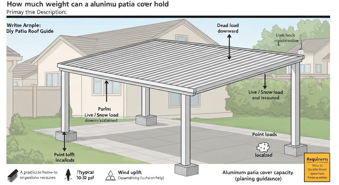
The honest caveats before you rely on any number
No single psf figure applies to every aluminum patio cover. A 10 psf kit bought at a home improvement store is engineered as a system, and every component in that system is sized to hit that number together. Swap out one beam, extend the span by two feet, or skip a post, and that rating goes out the window. Manufacturer ratings also assume correct installation, proper footings, and compliance with local code. In high-snow or high-wind zones, 10–20 psf is almost certainly not enough, and many jurisdictions require a site-specific engineering submission before issuing a permit. Use the ranges in this article as planning guidance, not as a substitute for the manufacturer's actual load tables or a structural engineer's sign-off on a custom build.
How loads actually act on your patio cover
Before you can make sense of psf ratings, you need to know what kinds of loads are trying to push, pull, and bend your structure. There are four categories that matter for a patio cover.
Dead load
Dead load is the permanent weight of the roof itself: the aluminum panels, purlins, beams, posts, and any fasteners or gutters. For a typical lightweight aluminum patio cover assembly using 0.032"–0.040" formed panels, dead load is usually 2–4 psf. Heavier insulated panel systems or tile-topped structures push that higher. This load is always present and acts straight down.
Live load and snow load
Live load covers temporary loads: a worker walking on the roof during installation, accumulated rain, and in relevant climates, snow. The 2024 IRC requires that roof framing be designed for the greater of the roof live load from Table R301. The 2024 International Residential Code, Chapter 3 (R301 roof/snow/live-load requirement) requires roof framing be designed for the greater of the roof live load in Table R301.6 or the ground snow load in Table R301.2 2024 International Residential Code — Chapter 3 (R301 roof/snow/live-load requirement). 6 or the ground snow load from Table R301.2. In most mild-climate areas (Southern California, Florida, most of Texas), the code minimum roof live load is 20 psf. In mountain and northern states, ground snow loads of 30–100+ psf are common, and your cover must be designed for the converted roof snow load, not just a generic number. Snow sits on a roof as a sustained load, so it compounds with dead load and stresses beams much harder than a brief live load does.
Wind load
Wind is trickier because it acts both downward (pressure) and upward (uplift, or suction). On a low-slope patio cover, uplift is often the governing wind load case and it tries to pull the roof off its posts and connections. ASCE 7 is the national standard that sets the wind load calculation procedures, and your local jurisdiction will have a mapped design wind speed for your area (many counties moved to the ASCE Hazard Tool lookup in 2024–2025). A well-marketed 115 mph wind rating, like some Integra kit lines advertise, means the system was designed to resist those wind pressures as a whole, but only when installed correctly with proper anchors.
Point loads
Point loads are concentrated forces at specific locations: a ceiling fan hung mid-span, a heavy planter on a beam, or even the weight of someone leaning hard on a gutter. These are distinct from the uniform distributed loads that psf ratings address, and they can cause local failure even on a cover that technically meets its psf rating. A 50 lb ceiling fan hung from a thin-walled aluminum purlin mid-span is a very different problem than 50 lbs spread across the whole roof.
How loads travel through the structure
Every pound of load on the roof surface travels down a chain: panels transfer load to purlins, purlins transfer to beams or rafters, beams transfer to posts, and posts transfer to footings. Each step in that chain has to be strong enough, and the connections between steps have to work too. A beefy beam sitting in flimsy post caps will fail at the caps. A perfectly sized post sitting on a 6-inch concrete pad in sandy soil will sink. The whole chain matters.
What controls how much load your aluminum cover can take
These are the variables that determine whether your cover handles 10 psf or 30 psf. Change any one of them and the capacity changes.
- Extrusion profile and wall thickness: Heavier-wall extrusions (0.060"–0.125" wall) in structural alloys like 6061-T6 carry far more load than thin architectural 6063 profiles. The Aluminum Design Manual (ADM 2020) published by the Aluminum Association is the reference for allowable stresses, and 6061-T6 has a typical yield strength around 35–40 ksi versus 6063's 15–25 ksi depending on temper.
- Span between supports: This is the biggest single factor. Beam capacity drops steeply as span increases — a beam rated at 30 psf over an 8 ft span might only handle 12 psf over a 14 ft span. This mirrors the W-pan load table data showing ratings for .032" panels dropping from ~42 psf at an 8 ft projection to the low teens at 12 ft.
- Beam depth and section modulus: A deeper beam resists bending much better than a shallower one of the same wall thickness. Doubling beam depth quadruples the section modulus.
- Post spacing: Closer posts shorten beam spans and increase capacity. Posts spaced 6–8 ft apart support a much stiffer system than posts at 12–16 ft.
- Roof style: A flat or low-slope patio cover concentrates loads more than a gable roof that sheds snow. Gable roofs also handle wind loading differently from lean-to covers attached to a house.
- Connection quality: Bolted connections with proper hardware rated for aluminum are critical. Self-tapping screws into thin aluminum flanges are not a substitute for through-bolts or engineered post brackets in load-bearing applications.
- Local code requirements: Your jurisdiction sets the minimum design loads. In ASCE 7 high-wind zones (Coastal Southeast, Gulf Coast, parts of the Midwest), the design wind speed alone may govern the structural design more than snow ever would. Many counties adopted the ASCE Hazard Tool in 2024–2025 for site-specific parameters.
Realistic capacity ranges: light, medium, and heavy-duty systems
Rather than a single number, think in three tiers. These are planning-level ranges based on common manufacturer data and engineering practice. Actual capacity for any specific product depends on the manufacturer's tested or engineered specs for that assembly.
| System Type | Typical Total Load Rating | Common Applications | Example Products/Approach |
|---|---|---|---|
| Light-duty kit | 10–15 psf | Mild climates, no snow, decorative shade only | Basic Integra 10 psf kits, thin-wall architectural extrusions, .032" W-pan at longer spans |
| Medium-duty residential | 20–30 psf | Most of the continental US, moderate snow, standard permits | Integra 20 psf kits, Alumawood standard engineering packet, .040" W-pan at 8–10 ft spans |
| Heavy-duty engineered | 30–60+ psf | Snow country, high-wind coastal zones, large spans | Custom-engineered aluminum, 6061-T6 structural beams, engineered post footings, stamped drawings required |
The Amerimax/Alumawood engineering packets commonly used in low-snow jurisdictions specify 10–20 psf as the nominal residential live load. For mountain or northern states with 30–100+ psf ground snow loads, you are firmly in the heavy-duty engineered tier and need stamped drawings from a licensed structural engineer. Most DIY homeowners doing their own patio cover in the Sun Belt or Pacific Northwest lowlands will land in the medium-duty range.
How to calculate the load capacity you actually need
Here is the practical process I use when planning a new cover or checking whether an existing one is adequate. You are not producing a stamped engineering drawing, but you are doing enough math to have an informed conversation with a manufacturer or building department, and to know whether your planned system is in the right ballpark.
- Step 1 — Find your design loads. Look up your local ground snow load (Pg) and design wind speed (V) using the ASCE Hazard Tool (hazards.atcouncil.org) or your local building department's published values. Note the code-minimum roof live load for your jurisdiction (commonly 20 psf in mild climates). Your design snow load (Ps) is derived from Pg with a roof factor; for a simple flat or low-slope patio roof, a conservative starting point is to use Pg directly if it is less than 20 psf, or calculate Ps = 0.7 × Ce × Ct × I × Pg where Ce, Ct, and I are exposure, thermal, and importance factors (typically 1.0 each for a standard residential patio in an open suburban yard).
- Step 2 — Calculate total design load. Total load = Dead load + max(Live load, Snow load). Use at least 2–4 psf for dead load on a typical aluminum panel assembly, or use the manufacturer's listed assembly weight. Example: 3 psf dead + 20 psf live = 23 psf. Round up to the nearest standard tier (in this case, a 30 psf-rated system gives you a safety margin).
- Step 3 — Determine tributary areas. For each beam, the tributary width is half the span on each side to the next support (or to the edge). Tributary area = beam length × tributary width. For each post, the tributary area is the product of beam spacing and post spacing.
- Step 4 — Convert psf to line loads and reactions. Multiply your total design load (psf) by the tributary width (ft) to get a uniform line load in pounds per linear foot (plf). Example: 23 psf × 4 ft tributary width = 92 plf on the beam. For a simply supported beam of span L, the maximum reaction at each end (and therefore the load on each post) = (line load × span) / 2.
- Step 5 — Check against manufacturer specs or section properties. Compare your calculated beam reaction to what the manufacturer's load table shows for that beam size and span. If you are working from raw extrusion data, you need the section modulus (S) and allowable bending stress from the Aluminum Design Manual, then check that the applied moment M = wL²/8 does not exceed the allowable moment = S × Fb, where Fb is the allowable bending stress for your alloy.
- Step 6 — Check deflection. IRC Chapter 8 commonly applies L/240 for live load deflection and L/180 for total load deflection. Aluminum's modulus of elasticity is about 10,000 ksi (69 GPa), roughly one-third of steel. For a simply supported beam: live-load deflection = 5wL⁴/(384EI). If this exceeds L/240, you need a deeper or heavier section.
- Step 7 — Size your posts and footings. Each post carries the sum of all beam reactions framing into it. Check the post's axial load capacity (column buckling controls for slender aluminum tubes). Footing size is governed by the soil bearing capacity, which your local code or a soil test will specify.
Worked example 1: small single-span cover (12 ft x 10 ft)
Scenario: You are building a simple lean-to patio cover attached to the house on one side, with a single beam carried by two posts on the outer edge. The cover is 12 ft wide (parallel to the house) and has a 10 ft projection (the dimension from house to outer beam). Location: suburban Portland, Oregon (moderate rain, low snow by Pacific Northwest valley standards). Ground snow load Pg = 25 psf per ASCE Hazard Tool lookup.
- Dead load: 3 psf (aluminum panel assembly per manufacturer's data sheet).
- Roof live load: 20 psf (IRC Table R301.6 for low-slope roof).
- Snow load check: Ps = 0.7 × 1.0 × 1.0 × 1.0 × 25 = 17.5 psf. The live load of 20 psf governs.
- Total design load: 3 + 20 = 23 psf. Use a system rated to at least 25–30 psf to maintain margin.
- Tributary width for the outer beam: The outer beam supports load from halfway across the 10 ft projection = 5 ft tributary width. (The inner half transfers to the ledger at the house wall.)
- Line load on outer beam: 23 psf × 5 ft = 115 plf.
- Outer beam span: 12 ft between the two posts.
- Beam reaction at each post: (115 plf × 12 ft) / 2 = 690 lbs per post.
- Each post carries 690 lbs axial load. A 3.5" × 3.5" aluminum structural tube with a wall thickness of 0.125" in 6061-T6, at a height of 9 ft, handles this easily (allowable axial load well over 5,000 lbs for typical column lengths at this section). A 4×4 wood post would also work here.
- Footing check: 690 lbs on a footing in average soil (1,500 psf bearing capacity) requires a footing area of at least 690/1,500 = 0.46 sq ft, or roughly a 9"×9" pad. A standard 12"×12"×12" concrete footing exceeds this comfortably.
- Result: A medium-duty 20–30 psf rated manufacturer kit (e.g., Integra 20 psf system sized for a 10 ft projection and 12 ft width) is appropriate for this application in Portland.
Worked example 2: larger multi-span cover (20 ft x 16 ft, two intermediate posts)
Scenario: A freestanding patio cover, 20 ft wide and 16 ft deep, with a center row of two intermediate posts creating two 8 ft spans in the depth direction, and post spacing of 10 ft along the 20 ft width. Location: Denver, Colorado. Ground snow load Pg = 35 psf (from ASCE Hazard Tool). Design wind speed 115 mph (Exposure B).
- Dead load: 4 psf (heavier aluminum assembly with gutters and purlins).
- Roof live load: 20 psf (IRC minimum).
- Snow load: Ps = 0.7 × 1.0 × 1.0 × 1.0 × 35 = 24.5 psf. Snow governs over live load.
- Total design load: 4 + 24.5 = 28.5 psf. Round up and design for 30 psf.
- Layout: Posts at the four corners plus two intermediate posts at mid-width (10 ft spacing), creating a 2-row × 3-bay grid. Spans in the depth direction are 8 ft each. Spans in the width direction are 10 ft.
- Tributary area per intermediate post: 10 ft (width spacing) × 8 ft (average of half-spans on each side = 4 + 4 ft) = 80 sq ft.
- Load on intermediate post: 30 psf × 80 sq ft = 2,400 lbs.
- Tributary area per corner post: 5 ft (half of 10 ft) × 8 ft (half of 16 ft) = 40 sq ft.
- Load on corner post: 30 psf × 40 sq ft = 1,200 lbs.
- Beam check (10 ft span, tributary width 8 ft, total load 30 psf): Line load = 30 × 8 = 240 plf. Maximum moment = 240 × 10² / 8 = 3,000 ft-lb = 36,000 in-lb. A 6" deep aluminum structural beam (6061-T6) with a section modulus of approximately 3.5–4.0 in³ has an allowable moment around 3.5 × 21,000 = 73,500 in-lb (using ADM allowable Fb ≈ 21 ksi for 6061-T6 beams). This provides substantial margin.
- Deflection check: Live load only (24.5 psf × 8 ft = 196 plf) over a 10 ft span with E = 10,000 ksi and I ≈ 10.5 in⁴ for the beam: delta = 5 × (196/12) × (120)⁴ / (384 × 10,000,000 × 10.5) ≈ 0.27 in. Limit is 120/240 = 0.50 in. Passes.
- Comparison to manufacturer ratings: This system requires a 30 psf-rated manufacturer kit or a custom engineered assembly. Integra's 20 psf kit would be undersized here. You would need to source a manufacturer offering 30 psf kits for a freestanding structure of this size, or use a locally engineered custom aluminum system. In Denver, a permit submittal with stamped drawings is almost certainly required.
Post spacing, number of posts, and sizing
Post spacing is one of the most common places I see DIY patio covers go wrong. For step-by-step guidance on setting, anchoring, and pouring footings for posts, see how to install patio cover posts. People space posts at whatever looks good, or wherever they can dig without hitting irrigation lines, rather than letting the beam span capacity set the spacing. If you're wondering how many posts for patio cover you need, let the beam span capacity drive spacing rather than appearance. Here is how to think about it correctly.
Ledger-attached (lean-to) layouts
On a ledger-attached cover, the house ledger acts as one beam support, and the outer beam carries the other end of the rafters. The outer beam spans between posts along the front of the cover. For a 20 psf system with typical medium-weight aluminum beams, post spacing of 8–10 ft is the normal working range for most kit systems. Pushing to 12 ft requires a noticeably heavier beam section. For a 10 ft × 12 ft cover attached to the house, two posts (one at each end of the outer beam) is typically sufficient. For a 10 ft × 20 ft cover, three posts (8–10 ft spacing) are more appropriate.
Freestanding layouts
A freestanding cover has beams on all sides and often intermediate beams running across the depth. Both the front-to-back and side-to-side beam spans need to be checked. A freestanding 16 ft × 20 ft cover will typically need at minimum four corner posts plus intermediate posts to keep beam spans under 10–12 ft. The exact number of posts ties directly to your beam capacity, which is why the post count article and post spacing article are worth reading alongside this one.
Recommended post sizes
| Load on Post (lbs) | Aluminum Post Option | Wood Equivalent | Notes |
|---|---|---|---|
| Up to 1,500 lbs | 3" × 3" aluminum tube, 0.125" wall, 6061-T6 | 4×4 Doug Fir | Common for small lean-to covers, 8–9 ft height |
| 1,500–3,500 lbs | 3.5" × 3.5" or 4" × 4" aluminum tube, 0.125"–0.188" wall, 6061-T6 | 4×6 or 6×6 Doug Fir | Standard for medium residential freestanding covers |
| 3,500–6,000 lbs | 4" × 4" or 5" × 5" aluminum tube, 0.188"–0.250" wall, 6061-T6 | 6×6 or 6×8 Doug Fir | Heavy-duty or high-snow/wind applications, verify with engineer |
| Over 6,000 lbs | Engineered aluminum column or wide-flange section | Consult engineer | Requires stamped drawings and engineered footings |
Note that post height matters a lot for slenderness. A 4" aluminum tube that handles 4,000 lbs at 8 ft height may only handle 2,500 lbs at 12 ft due to column buckling. Always check the manufacturer's column load table or run a buckling check if your posts are unusually tall. For quick rules of thumb on post dimensions and footing sizing, see our guide on what size post for patio cover.
Rules of thumb for planning and retrofit
- Keep beam spans at or under 10 ft for standard residential 20 psf kit systems. Going to 12 ft usually requires stepping up to a heavier beam section.
- Space posts no more than 10 ft apart along the beam for most residential aluminum covers. 8 ft spacing gives you more margin for future upgrades like ceiling fans or heaters.
- For a retrofit (adding a post to an existing cover), adding an intermediate post under a sagging mid-span beam is one of the highest-value structural improvements you can make.
- Minimum 3.5" × 3.5" post cross-section for any post carrying more than one tributary bay of load.
- Always anchor posts to footings with through-bolted post bases, not just set in concrete. Uplift forces from wind can exceed the downward load in some cases.
When and how to reinforce or upgrade an existing cover
If you have an existing aluminum patio cover that sags, deflects visibly under rain, rattles in wind, or was built before your local code adopted current wind speed maps, it is worth checking rather than assuming it is fine. Common signs of an under-capacity cover include: noticeable mid-span sag in beams (more than about L/180 of the span), loose or missing fasteners at post caps or ledger connections, posts that visibly lean or have settled footings, and panels that flex or buckle under moderate snow.
The most practical reinforcement steps, in order of impact: (1) Add an intermediate post under the beam with the most sag. This immediately halves the effective span and roughly quadruples the beam's load capacity. (2) Sister a heavier beam alongside the existing one. Aluminum can be through-bolted together to create a composite section. (3) Upgrade connections at the ledger and post tops. Adding proper through-bolted post caps or hurricane ties dramatically improves the uplift resistance of an otherwise lightly-fastened cover. (4) Re-check and if necessary upgrade footings. A post sitting on an undersized pad that has started to sink needs a new footing, not just shimming.
DIY installation and attachment: what matters most for load capacity
The load capacity of an aluminum cover is only as good as the installation. These are the points where I have seen DIY projects fail structurally, even when the materials were rated correctly. For step-by-step guidance on the actual build process, see our detailed guide on how to install a patio cover (internal reference: 10e37976-8a4d-480e-a37b-3a7b2b32c7be).
- Ledger attachment: The ledger must be bolted to the house's structural framing (rim joist or wall studs), not just to sheathing or trim. Use 1/2" lag screws or through-bolts at 16" spacing minimum, and make sure you hit solid framing. A flashing detail over the ledger is mandatory, not optional.
- Post anchors: Use code-approved post base hardware (Simpson Strong-Tie or equivalent) that provides both compression and uplift resistance. The anchor bolts must be embedded in concrete to the manufacturer's specified depth, typically 3.5"–7" depending on the connector.
- Footing depth: Must extend below the frost line in cold climates. In Denver (frost depth ~36"–42"), a surface-mounted footing pad is not acceptable. In Phoenix, a shallower footing is fine but must still meet local code.
- Beam-to-post connections: Kit systems use proprietary post caps; make sure all fastener holes are filled with the correct fasteners. For custom builds, use rated post caps with the fastener schedule specified by the hardware manufacturer.
- Purlin-to-beam connections: Every purlin should be fastened at both ends. Self-tapping screws in proper shear are fine for panel-to-purlin connections, but structural purlins in load-bearing positions deserve through-bolted or welded connections.
- Aluminum-to-aluminum corrosion: Use stainless steel or aluminum fasteners, not plain steel or zinc-plated hardware that will galvanically corrode the aluminum within a few years.
Pre-installation safety checklist
- Permit obtained and approved drawings on site before any footing is poured.
- Design loads verified against local ground snow load and wind speed (use ASCE Hazard Tool or building department values, not generic national charts).
- Footing size and depth confirmed against local frost depth and soil bearing capacity.
- All lumber (if used) pressure-treated for ground contact where required.
- Post bases rated for both vertical load and uplift, anchored per manufacturer's instructions.
- Ledger through-bolted to structural framing with proper flashing installed.
- All beam-to-post and purlin-to-beam connections completed with correct fastener count.
- Inspection scheduled before covering footings and before finishing roof panels.
When to call the manufacturer, and when to call an engineer
If you are buying a manufacturer kit system like Integra, start with their technical team. For products like the Integra line, the manufacturer publishes load ratings (10 psf and 20 psf kit options are common, with wind ratings such as 115 mph addressed in their product Q&A), and they will often specify which kit is appropriate for your projection, width, and local loads if you give them your design parameters. For brand-specific systems like the Integra cover, the installation booklet is your structural bible. Deviating from it voids the rated capacity. The installation guide for systems like Integra is a good place to start before tackling any custom modifications.
Call a licensed structural engineer when: you are in a high-snow jurisdiction (Pg over 30 psf), you are in a coastal high-wind zone (design wind speed over 130 mph), your cover is larger than about 400 sq ft, you are attaching to a home with an unusual wall type (ICF, SIP, stucco over wood framing with no accessible rim joist), your building department requires stamped drawings for the permit, or your existing cover shows signs of structural distress and you are not sure why. An engineer's review of a residential patio cover typically costs $300–$800, which is cheap insurance against a collapsed structure.
Common mistake here: people think a structural engineer is only for big commercial projects. For a patio cover in Denver or Tahoe City, getting those drawings stamped is just part of getting a permit, and many municipalities will not accept a DIY drawing no matter how accurate. Build that fee into your budget from the start.
Aluminum vs. other materials: a quick comparison
If you are still deciding whether aluminum is the right choice for your cover, here is how it stacks up against wood and steel on the factors that affect load capacity and long-term performance.
| Factor | Aluminum | Wood (Doug Fir/SPF) | Steel |
|---|---|---|---|
| Weight (dead load) | Very light (2–4 psf assembly) | Moderate (5–10 psf assembly) | Heavier (3–8 psf depending on section) |
| Strength-to-weight ratio | Excellent | Good | Very good |
| Modulus of elasticity | ~10,000 ksi (deflects more than steel) | ~1,700–1,900 ksi (Douglas Fir) | ~29,000 ksi (stiff) |
| Corrosion resistance | Excellent (anodized or powder-coated) | Requires treatment, paint | Requires coating; prone to rust |
| Ease of DIY fabrication | Kit systems easy; custom harder (no field welding) | Easy to cut and fasten on site | Difficult without welding equipment |
| Cost | Moderate to high for structural grades | Low to moderate | Moderate; higher for custom |
| Span capacity | Good with proper sections; lower modulus limits spans vs. steel | Very good with large timber sections | Best for long spans |
Recommendation: For most residential patio covers in mild to moderate climates, aluminum kit systems offer the best combination of low maintenance, light dead load, and straightforward DIY installation. If you are spanning more than 14 ft without intermediate posts, or carrying heavy loads in snow country, either a custom engineered aluminum system or a steel beam with aluminum infill panels is worth considering. Wood is the easiest to source and modify on the fly, but it requires more ongoing maintenance and heavier post and footing sizing.
FAQ
Quick answer: how much weight can an aluminum patio cover safely carry?
Typical manufactured aluminum patio covers and kit systems are commonly rated by manufacturers in the range of about 10–30 psf (pounds per square foot) for roof/live loads. Lightweight panel-only dead loads are small (~2–4 psf). In low‑snow, low‑wind areas many kits are sold at 10–20 psf; in higher‑snow areas engineered systems or upgrades of 30 psf or more are used. Important caveats: these are general ranges — actual safe capacity depends on the specific extrusion/profile, member spans, post spacing, roof style, attachments and local code (snow and wind). Always use manufacturer load tables or a structural engineer for nonstandard spans, heavy snow zones, added finishes or storage loads.
What types of loads act on a patio cover and how are they transferred to beams and posts?
Common loads: dead load (weight of panels, purlins, fasteners, gutters), live/load‑for‑service (temporary loads like snow, maintenance, contractors), and wind loads (uplift and lateral). Load transfer: roof panels or purlins take the uniform roof load (psf) and tributary it to supporting rafters/beams as line loads (plf) or point loads at bearing connections. Beams transfer the loads into posts as axial and bending loads; posts transfer to footings/anchors and then into the ground. Snow and live loads act downward and control member strength and deflection; wind can cause uplift and lateral shear — attachment details and connection capacities are critical to resist uplift.
Which factors most control how much load an aluminum cover can carry?
Key factors: 1) Profile/section properties and alloy (extrusion thickness, flange depth, alloy temper), 2) Member spans and tributary width, 3) Beam and purlin sizes and connection details, 4) Post number, spacing and size and footing capacity, 5) Roof style (single beam span, multiple purlins, cathedral/hip), 6) Dead vs snow vs wind demands at the site (site ground‑snow and design wind per ASCE/municipal requirements), 7) Attachment to the house or ledger design, and 8) Local code and deflection limits (e.g., typical L/240 live, L/180 total).
How do I convert a manufacturer psf rating to the load on a beam or post? (step‑by‑step)
1) Determine the design psf (use the controlling case: ground snow or roof live + code wind as required). 2) Find the tributary width for the beam/rafter (half the distance to adjacent members on both sides, or the panel width supported). 3) Multiply psf × tributary width to get an equivalent line load (plf). Example: 20 psf × 4 ft tributary = 80 plf. 4) For a cantilever or simply supported span, convert plf to maximum bending moment and shear using standard beam formulas (M = wL^2/8 for uniform load on simple span). 5) Check member allowable moment (section modulus × allowable stress) and deflection (Δ = 5wL^4/(384EI) for uniform load on simple span) against alloy limits and code deflection limits. 6) For posts, sum tributary reactions to find axial load and check buckling/soil bearing/footing capacity.
Worked example 1 — checking a simple aluminum beam for a 12 ft projection at 20 psf
Given: design load = 20 psf, tributary width per beam = 4 ft (panels or purlin spacing), beam span L = 12 ft. Step 1: line load w = 20 psf × 4 ft = 80 plf. Step 2: max bending moment (simply supported) M = wL^2/8 = 80×12^2/8 = 80×144/8 = 1440 ft‑lb = 17,280 in‑lb. Step 3: pick candidate aluminum section & find section modulus S (from manufacturer or ADM). Example: if S = 2.5 in^3 and allowable bending stress for given alloy/temper is ~8–12 ksi (manufacturer/ADM gives specific values), allowable moment = S×Fallow. If Fallow = 10 ksi → Mallow = 2.5×10,000 = 25,000 in‑lb, which is >17,280 in‑lb so moment OK. Step 4: check deflection: use E ≈ 10,000 ksi for alloy; compute Δ and compare to L/240 = 12 ft/240 = 0.6 in allowable for live load. If computed Δ < 0.6 in, deflection OK. Note: this example uses approximate allowable stress; always use exact section properties and allowable stresses from the Aluminum Design Manual or manufacturer's data.
Worked example 2 — sizing post reactions for the same beam
Same scenario: w = 80 plf across a 12 ft span. Total uniformly distributed load W = w×L = 80×12 = 960 lb carried by that beam. With two support posts at beam ends, each reaction ≈ 480 lb (neglect tributary share from adjacent beams). If posts are spaced to carry multiple beams, sum the tributary loads from each beam. Check post axial capacity: for a modest aluminum post or comparable wood post, 480 lb is small — posts are typically sized for thousands of pounds. For footing/anchor: ensure soil bearing or concrete pier can support the summed vertical load plus frost/settlement requirements. For uplift or lateral checks, include wind loads and eccentricity from connection detailing.