
Installing patio cover posts comes down to four decisions made before you ever dig a hole: whether your cover attaches to the house or stands free, what material your posts are made of, how big and how far apart they need to be, and how deep your footings go. Get those four things right, and the rest of the job is straightforward carpentry. Get them wrong, and you end up with a wobbling structure, a failed inspection, or worse. This guide walks through every one of those decisions with real numbers, code references, and the kind of mistakes I've watched people make (and made myself early on) so you can avoid them. For step-by-step instructions, see how to install a patio cover.
How to Install Patio Cover Posts: Sizes, Spacing & Footings

Celia Vaughn
18 Jul 2026
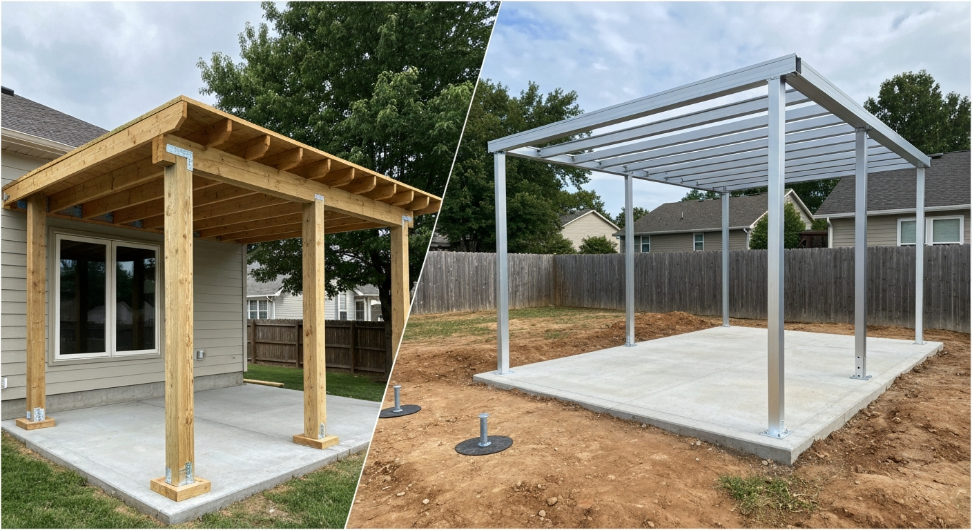
What this guide covers and the decisions you need to make first
Before you buy a single post or rent a post-hole digger, you need to settle on a handful of choices that affect everything downstream. The structure type (ledger-attached versus free-standing) determines your footing count, your beam layout, and your permit complexity. Your post material affects cost, longevity, and how you connect the roof framing. Your post size and spacing determine whether the structure passes a load check. And your footing depth is non-negotiable once frost depth and soil conditions enter the picture. This article covers all of that, plus anchors, load capacity, and an honest look at when a permit and inspector are worth every dollar.
- Ledger-attached vs. free-standing: which layout fits your site
- Post materials: wood, aluminum, and steel compared by cost, weight, and longevity
- Post sizing: 4x4, 6x6, and metal tube equivalents for common roof spans
- Spacing and post count for patio covers ranging from 10x12 to 16x20 and beyond
- Footing specs: depth, diameter, concrete strength, rebar, and frost rules
- Anchors and post bases: Simpson bases, epoxy anchors, and bolt sizing
- Load capacity: reading snow and wind loads and applying them before you build
- Step-by-step installation for both attachment types
- Permit, code, and safety checkpoints
- When to stop DIYing and call a structural engineer or licensed contractor
Ledger-attached vs. free-standing: which one is right for your project
A ledger-attached patio cover fastens one side of its beam directly to the house framing, so you only need posts along the outer edge. A free-standing structure has posts on all four corners (and often in between) with no connection to the house at all. Most homeowners default to ledger-attached because it uses fewer posts and materials, but free-standing is sometimes the smarter choice and occasionally the only legal option.
Choose ledger-attached when: the house wall gives you solid lumber to fasten into (rim joist or band joist, not just sheathing or foam), you want to minimize post count and cost, and you are willing to properly flash the connection point. IRC Section R507.9 requires that ledger-attached structures be positively anchored to the primary structure for both vertical and lateral loads using 1/2-inch lag screws or 1/2-inch through-bolts in a two-row staggered pattern per Table R507.9.1.3(1), or approved structural screws like Simpson SDWS, FastenMaster LedgerLOK, or GRK RSS installed per manufacturer spacing. Continuous corrosion-resistant flashing between the ledger and house wall is mandatory under IRC R703.4. Skip the flashing and you're looking at rot in the rim joist within five to ten years.
Choose free-standing when: your house has a stucco, EIFS, or stone veneer exterior that is difficult to flash properly; when the HOA or local code restricts attachments to the primary structure; when you want to build on a separate concrete pad away from the house; or when the house framing is not accessible without major demolition. Free-standing covers require footings at every corner plus intermediate posts, which adds cost, but they're structurally self-contained and don't carry the water-intrusion risk that a poorly flashed ledger does.
| Factor | Ledger-Attached | Free-Standing |
|---|---|---|
| Post count | Fewer (outer edge only) | More (all sides) |
| Footing count | Lower | Higher |
| Material cost (relative) | Lower | Higher |
| House wall attachment required | Yes — flashing critical | No |
| Good for stucco/EIFS walls | Rarely | Yes |
| Permit complexity | Moderate (ledger inspection) | Moderate (footing inspection) |
| Water intrusion risk | Higher if flashing fails | None at house wall |
| Lateral stability | House provides it | Must be built into structure |
Wood, aluminum, and steel posts: what each one actually costs and lasts
The post material you pick isn't just an aesthetic call. It affects how you cut and fasten the framing, what connectors you can use, how much maintenance you'll do over the years, and what your local lumber yard or metal supplier actually stocks. Here's an honest comparison.
Pressure-treated wood
Pressure-treated (PT) lumber is the most DIY-friendly option. You can cut it with a standard miter saw, fasten it with common hardware, and find it at any home center. A 4x4x10 PT post runs roughly $15 to $25 depending on your region and grade, and a 6x6x10 runs $35 to $60. The downside: PT lumber in ground-contact or near-concrete applications corrodes standard zinc fasteners, so you need hot-dipped galvanized or stainless hardware throughout. Modern PT lumber uses micronized copper azole (MCA) or copper azole (CA) preservatives, which are more corrosive to metal than the older CCA formulas. Use ZMAX or stainless connectors from Simpson or USP, not standard galvanized. Expected service life in a well-built, properly finished patio cover is 20 to 40 years, longer if you paint or seal the wood every few years.
Aluminum posts
Aluminum posts are the go-to for kit-based patio cover systems like Alumawood, Stratco, and Integra. They're lightweight, won't rot or rust, and come pre-painted in standard colors. Typical aluminum post sizes for residential patio covers are 3x3-inch or 4x4-inch square tube in 0.060- to 0.080-inch wall thickness. Material cost is higher than wood, roughly $40 to $90 per 10-foot post for standard residential tube stock, but you save on long-term finishing. The tradeoff: aluminum is softer and dents more easily than steel, requires specific aluminum-rated fasteners (stainless or aluminum pop rivets, not zinc screws), and has lower bending strength than an equivalent-sized wood post, so you can't simply swap dimensions. If you're building an Integra or similar proprietary system, the manufacturer's installation guide specifies the exact post tube size and base hardware, and you should follow that spec precisely. For step-by-step, system-specific guidance, see how to install Integra patio cover (22f9f235-4d00-47aa-bb4b-743a703a2b49).
Steel posts
Steel square tube or pipe posts offer the highest strength-to-size ratio of the three options and are common in commercial-grade patio covers and heavy pergolas. A 3x3 or 4x4 steel square tube (11-gauge wall, about 0.120 inch) can carry significantly more load than wood or aluminum at the same cross-section. Cost runs $60 to $150+ per 10-foot post for structural steel tube, and they require welding or bolted connections that most DIYers aren't equipped for. Unless you're fabricating a custom steel structure or live in a high-wind or heavy-snow area where the engineer specifies steel, wood or aluminum will handle the vast majority of residential patio covers without issue.
| Attribute | Pressure-Treated Wood | Aluminum | Steel |
|---|---|---|---|
| Typical post cost (10 ft) | $15–$60 | $40–$90 | $60–$150+ |
| DIY-friendly cutting | Yes — standard miter saw | Yes — miter saw with metal blade | Difficult — needs cutting wheel or saw |
| Rot/rust resistance | Moderate (with treatment) | Excellent | Needs paint/coating |
| Structural strength | Good | Moderate | Best |
| Fastener requirements | ZMAX or SS hardware | SS or aluminum rivets | Bolted or welded |
| Maintenance | Paint/seal every 2–5 years | Minimal — wash occasionally | Touch up coating as needed |
| Typical service life | 20–40 years | 30–50+ years | 50+ years |
| Best for | Most DIY wood covers | Kit systems, low-maintenance | Heavy loads, custom builds |
For most DIY patio cover projects, pressure-treated wood posts are the practical default unless you're using a kit system that specifies aluminum. Wood is cheaper upfront, easy to work with standard tools, and strong enough for any residential span when properly sized.
What size posts you actually need
Post sizing is driven by two things: the height of the post and the tributary load it carries (meaning how much roof area drains its weight onto that one post). For most residential patio covers with post heights under 10 feet and modest roof spans, the options are 4x4, 6x6, or their aluminum and steel equivalents. For more detail on choosing the right dimensions, see what size post for patio cover.
4x4 wood posts
A 4x4 wood post (actual 3.5 x 3.5 inches) works for patio covers up to roughly 8 feet tall carrying limited tributary area, typically up to about 36 square feet of roof per post in low-snow, low-wind zones. The AWC DCA-6 prescriptive deck guide shows that 4x4 posts are acceptable up to 8 feet tall when supporting modest loads, but they provide very little resistance to lateral (sideways) racking forces without additional bracing. See AWC, Prescriptive Residential Wood Deck Construction Guide (DCA‑6) (span/footing/post tables) for the prescriptive joist, beam, post and footing tables that support these limits AWC — Prescriptive Residential Wood Deck Construction Guide (DCA‑6) (span/footing/post tables). If your cover is free-standing and you're relying on the posts alone for lateral stability, go to 6x6 or add knee braces and diagonal bracing between posts.
6x6 wood posts
A 6x6 post (actual 5.5 x 5.5 inches) is the right call for posts over 8 feet tall, for corner posts on free-standing covers, for posts carrying more than 36 to 40 square feet of tributary roof area each, or anywhere in a moderate-to-heavy snow or high-wind zone. I default to 6x6 for any free-standing patio cover because the extra material cost is small compared to the stiffness and peace-of-mind you gain. A 6x6x10 PT post at $40 to $60 is not the place to economize.
Double posts and built-up posts
For very wide spans or tall covers, you can use double 2x6 or 2x8 built-up posts (two boards face-nailed together), which can match or exceed the section properties of a solid 4x4 or 6x6. Built-up posts are also useful when you need to run utilities through the post cavity or match existing framing dimensions. Make sure to nail them together with 16d (3.5-inch) nails at 12-inch spacing in a staggered pattern so they act as a single unit.
Aluminum and steel tube equivalents
For aluminum kit systems, follow the manufacturer's spec first and foremost. Most residential aluminum patio cover systems use 3x3 or 4x4 square tube. For custom steel work, a 3x3 x 11-gauge steel square tube carries loads well beyond what a 4x4 wood post handles, but sizing steel properly really does require an engineer's calculation for anything beyond a simple low-load lean-to.
| Post Size | Max Recommended Height | Approx. Max Tributary Area (low-load zones) | Best Use Case |
|---|---|---|---|
| 4x4 PT wood | Up to 8 ft | ~36 sq ft per post | Ledger-attached, light loads, low wind/snow |
| 6x6 PT wood | Up to 12–14 ft | ~60–80 sq ft per post | Free-standing, tall, moderate load zones |
| 3x3 aluminum tube (0.080") | Up to 10 ft | Per manufacturer spec | Kit systems (Alumawood, Integra, etc.) |
| 4x4 aluminum tube (0.080") | Up to 12 ft | Per manufacturer spec | Heavier kit systems or custom aluminum builds |
| 3x3 steel square tube (11-ga) | Up to 14 ft | High — engineer to confirm | Heavy loads, high-wind/snow zones, custom builds |
| Double 2x6 built-up | Up to 10 ft | Similar to 4x4 solid | Matching existing framing, utility runs |
Spacing and post count for common patio cover sizes
How far apart your posts are and how many you need depends on three things: the beam span between posts, the tributary load on each post, and what your local code allows prescriptively. The general rule for residential patio covers in standard load zones: keep beam spans to 12 feet or less between posts for wood construction without engineering, and limit post tributary areas to what the prescriptive tables in AWC DCA-6 and IRC R507 allow. If you need a quick answer on exact spacing, see the section on how far apart should posts be for a patio cover for typical post spacing by cover size and material. For spacing specifics by common patio cover size, see the table below.
For a ledger-attached cover, the house ledger acts as one 'beam line,' so you only need posts along the outer edge. For a 10x12 ledger-attached cover, that's typically two corner posts plus the ledger. If you're unsure, see our quick guide on how many posts for a patio cover to determine the exact post count for your dimensions and configuration. For free-standing covers, posts run along both long sides.
| Patio Cover Size | Structure Type | Typical Post Count | Typical Post Spacing (outer beam) | Notes |
|---|---|---|---|---|
| 10x12 | Ledger-attached | 2 outer posts | 10 ft apart | 4x4 or 6x6; single outer beam |
| 12x12 | Ledger-attached | 2 outer posts | 12 ft apart | 6x6 recommended at 12 ft beam span |
| 12x16 | Ledger-attached | 2–3 outer posts | 8 ft spacing with 3 posts | Intermediate post reduces beam size needed |
| 16x20 | Ledger-attached | 3–4 outer posts | 8–10 ft spacing | 6x6 posts; double beam likely needed |
| 12x12 | Free-standing | 4 corner posts | 12 ft x 12 ft grid | Add knee braces for lateral stability |
| 12x16 | Free-standing | 4–6 posts | 8 ft spacing on long side | Intermediate post on 16 ft runs |
| 16x20 | Free-standing | 6 posts | 8–10 ft grid | 6x6 throughout; engineer for heavy snow/wind |
| 20x24 | Free-standing | 6–8 posts | 8 ft max spacing | Engineer review strongly recommended |
A common mistake I see is spacing posts at 16 feet apart on a 4x4 post to save digging one extra hole. The beam spanning 16 feet between 4x4 posts will sag under snow load or even just its own weight over time. Keep outer beam spans at 12 feet or less for wood framing without an engineer reviewing your design, and use 6x6 posts when you're hitting that upper end of the range.
Footing depth, diameter, and concrete specs
Footings are the part of this project where there is no improvising. An undersized or too-shallow footing is both a structural failure waiting to happen and an automatic failed inspection. Here's what you need to know before you pour a drop of concrete.
Depth: frost line is the baseline
IRC Section R403.1.4 requires footings to extend at minimum 12 inches below undisturbed grade, and in any climate where the ground freezes, footings must extend below the locally adopted frost depth. Minimum footing depth and frost rule: IRC §R403.1.4 requires exterior footings to be placed not less than 12 inches below undisturbed ground surface and, where applicable, to extend below the locally adopted frost depth (or use an approved frost‑protection method such as a frost‑protected shallow foundation per IRC §R403.3) DeckMath — Deck footing requirements (IRC R403.1.4 referenced) summarizes that IRC §R403.1.4 requires exterior footings be placed at least 12 inches below undisturbed ground and, where applicable, to extend below the locally adopted frost depth.. This is not optional. Frost depth varies dramatically by region: it's 0 to 6 inches in southern California and Florida, 12 to 24 inches across much of the South and Pacific Northwest, 36 to 42 inches in the Midwest and Mountain West, and 48 to 60 inches in northern Minnesota, Wisconsin, and similar climates. Call your local building department or check your municipality's published frost depth map before you design your footings. Using a footing that stops 6 inches above the frost line means the ground will heave and shift seasonally, tilting posts and cracking the structure.
Diameter: match the load and soil
IRC R507.3 and the AWC DCA-6 prescriptive tables give footing diameters based on tributary area, design load, and assumed soil bearing capacity. For a conservative baseline using 1,500 psf soil bearing (a common default in IRC Table R401.4.1 for questionable or unverified soils), a post carrying 36 square feet of tributary area at 50 psf design load (40 psf live + 10 psf dead) needs a footing bearing area of at least 1.2 square feet, which is roughly a 14-inch diameter round footing. At 2,000 psf soil bearing (typical firm soil), that same post needs about a 12-inch diameter. Most inspectors will pass 12-inch Sonotube footings for typical residential patio cover posts in standard soil, but verify with your jurisdiction. For larger posts carrying 60 to 80 square feet of tributary area, step up to 16-inch or 18-inch diameter tube.
Concrete strength and reinforcement
Use 3,000 psi minimum compressive strength concrete for all footings and piers. This is standard PCA guidance and what most municipal specs require as a minimum. Pre-mixed bags (Quikrete 4000 or Sakrete 5000 work fine) or ready-mix at your local batch plant both hit this target. Add rebar when local code requires it or when your footing diameter is 16 inches or larger: a single #4 (half-inch) rebar running vertically down the center of the tube pier and hooking into a horizontal pad at the bottom is standard practice. For larger footings, two or three vertical #4 bars tied to a horizontal rebar cage in the base pad is typical. Always leave rebar sticking up far enough to engage the post base anchor bolt embedment zone if you're using a wet-set anchor.
Footing installation steps
- Lay out post locations with batter boards and string lines, checking for square by measuring diagonals (equal diagonals mean a square layout).
- Dig holes with a power auger or manual clamshell digger to the required depth plus 6 inches for a gravel drainage layer at the bottom.
- Add 4 to 6 inches of crushed gravel at the base and tamp it down.
- Set Sonotube (cylindrical cardboard form) in the hole so the top sits 2 to 4 inches above finished grade to prevent water pooling at the post base.
- Mix and pour 3,000 psi concrete, rodding or vibrating to eliminate air pockets.
- While concrete is still wet, set the anchor bolt or wet-set post base at exactly the right location (measured from your string lines), checking plumb with a level. This is your last chance to get position right.
- Allow concrete to cure a minimum of 24 to 48 hours before applying any load; 7 days for full working strength.
- Call for a footing inspection if required before the forms are removed or posts are set.
What often goes wrong here: people rush the wet-set anchor placement. Set the anchor, walk away to mix more concrete, come back, and the anchor has drifted. Use a template or a post bottom plate as a jig to hold the bolt pattern exactly while the concrete sets. A bolt pattern that is 1/4 inch off means you're drilling new holes in your post base or shimming, neither of which is a good look.
Anchors and post bases: the connection between footing and post
The post base is what connects the bottom of your post to the concrete footing or slab. It keeps the post from direct ground or slab contact (critical for preventing rot in wood), transfers vertical loads down into the concrete, and in many cases provides the only resistance to the post being pulled upward in a wind event. Choosing the right base and fastening it correctly is as important as the footing itself.
Wet-set vs. bolt-down bases
Wet-set bases (like the Simpson ABA or ABU series) embed an anchor strap or rod directly into wet concrete. They're the cleanest install and give you precise positioning, but only if you're careful during the pour. Bolt-down bases (like the Simpson PB, EPB, or MPBZ) fasten to a cured concrete slab or pier using anchor bolts or concrete screws. They're useful for retrofit work or when installing over an existing slab.
Simpson post base options
Simpson Strong-Tie's EPB (elevated post base) series and PB (post base) series are the workhorses for wood patio cover posts. The EPB44 (for 4x4 posts) and EPB66 (for 6x6 posts) elevate the post 1 inch above the slab surface, which is critical for drainage and rot prevention. Load values are published in Simpson's Wood Construction Connectors catalog: the EPB44 allows approximately 2,000 lbs of uplift and 1,500 lbs of lateral load with the published fastener schedule. The MPBZ (moment post base) is a specialty base designed to resist post rotation at the base, which is useful for free-standing structures where you need the post itself to provide lateral stability without knee braces. Most standard post bases do not resist rotation unless they're specifically rated for it, so check the catalog or ask your lumber yard's connector specialist before assuming a basic PB base gives you lateral stability.
Anchor bolts and concrete anchors
For wet-set applications, a standard J-bolt or L-bolt (typically 1/2 inch diameter, 6 to 10 inch embedment) cast into the footing is the most common approach. For bolt-down applications over existing cured concrete, you'll use expansion anchors or screw anchors. The Simpson Titen HD and Strong-Bolt series are ICC-ES evaluated for this purpose: a 1/2-inch Titen HD with 3-1/4-inch embedment into 3,000 psi concrete provides allowable tension loads well above what a typical residential post base needs, but you must respect the published minimum edge distance (typically 1-3/4 inches for the Titen HD) and minimum spacing between anchors. Hilti Kwik Bolt series anchors are an equally good alternative and carry similar ICC-ES evaluation reports. Epoxy anchors (like Hilti HIT-RE 500 or Simpson SET-XP) are used when anchor bolts need to be installed in cracked concrete or close to edges, because epoxy gives you more design flexibility than mechanical expansion anchors in those situations.
Common mistake: using concrete screws (like Tapcon) to fasten post bases on a residential patio cover. Tapcons are fine for light duty, but they are not rated for the tension (uplift) loads that post bases see in wind events. Use proper structural anchors with published tension and shear values for post base connections.
| Anchor Type | Best Application | Typical Size for Post Bases | Key Requirement |
|---|---|---|---|
| Wet-set J-bolt or L-bolt | New poured footings | 1/2" dia, 6–10" embedment | Must be set while concrete is wet |
| Simpson Titen HD (screw anchor) | Existing cured slab or pier | 1/2" x 3-1/4" min embedment | Minimum edge distance 1-3/4" |
| Simpson Strong-Bolt (wedge anchor) | Existing cured slab, high loads | 1/2" x 3-1/4" min embedment | Cracked-concrete reduction applies |
| Hilti Kwik Bolt TZ2 | Existing cured slab or pier | 1/2" x 3-1/4" min embedment | ICC-ES ESR-1917 rated |
| Epoxy anchor (SET-XP or HIT-RE) | Cracked concrete or close-to-edge | 1/2" all-thread, 3–4" embedment | Concrete must be clean and dry; temp range critical |
| Concrete screws (Tapcon) | Light-duty sill plates only | 3/16" or 1/4" | Not rated for post base uplift loads |
Load capacity: how to read snow and wind loads before you build
This is the section most DIY guides skip, and it's the one that gets people in trouble in snowy or coastal climates. Before you finalize post size, beam size, or footing diameter, you need to know two numbers: your site's ground snow load (in pounds per square foot) and your basic design wind speed (in miles per hour). For specific capacity examples and calculations, see how much weight can a patio roof hold. These drive every structural decision.
How to find your site loads
ASCE 7-22 is the standard reference for wind and snow load maps used in the current model codes. ASCE provides a free online GIS hazard tool where you can enter your address and get your site's ground snow load and basic wind speed. Your local building department will also have this information, and many published their adopted ground snow load and wind speed in the permit application or online plan review checklist. In areas where ASCE 7-22 has recently been adopted, pay attention to potential wind speed changes in coastal regions, which FEMA documented in their 2022 ASCE 7-22 highlights: some coastal and Gulf Coast areas saw significant increases in design wind speed under the updated maps.
Applying loads to post sizing and footings
For most of the southern US and Pacific Coast (ground snow load under 10 psf, wind speed under 110 mph), the prescriptive tables in AWC DCA-6 and IRC R507, which assume 40 psf live load and 10 psf dead load (total 50 psf), are conservative enough to use directly for residential patio cover post and footing sizing. You match your post's tributary area against the table, read off the required footing diameter, and size accordingly.
In areas with ground snow loads above 25 to 30 psf (mountain regions, the upper Midwest, New England), you need to convert the ground snow load to a roof snow load using the ASCE 7 formula (roof snow load = 0.7 x ground snow load for typical flat or low-slope roofs) and then check that against what your prescriptive post and footing table assumes. If the calculated load exceeds the table's assumption, either increase post and footing sizes conservatively or have a structural engineer review the design. This is genuinely not a judgment call to skip in a heavy-snow area.
Wood vs. aluminum cover load capacity
Aluminum patio cover panels and framing members are rated by manufacturers for specific load conditions, and you need to check those ratings against your actual site loads. For tested load limits and typical panel capacities, see how much weight can an aluminum patio cover hold. A typical aluminum lattice or solid patio cover panel is rated for 20 to 30 psf combined load in calm to moderate wind zones, but not all products are rated the same. If you're in a wind zone above 90 to 100 mph basic wind speed, check the product's ICC evaluation report or manufacturer load table before buying. Wood-framed patio covers can be sized to handle heavier loads by increasing beam and rafter dimensions, but aluminum kit systems are only as strong as what the manufacturer tested and rated. For heavier loads, consult the manufacturer or upgrade to a structural wood or steel frame.
A quick load-check example
Say you're building a free-standing 12x16 patio cover in Denver, Colorado. Denver's ground snow load is roughly 30 to 35 psf depending on exact elevation and local amendment. Roof snow load calculates to about 0.7 x 30 = 21 psf plus dead load. Your four corner posts each carry 48 square feet of tributary area (half the 12 ft width x half the 16 ft length = 6 x 8 = 48 sq ft). At a conservative 50 psf design load, each post carries 2,400 lbs in gravity alone. At Denver's actual snow-amplified loads, that number is higher. This is exactly the kind of situation where a 4x4 post is not adequate and 6x6 posts with properly sized footings (likely 16-inch diameter at minimum) are required. Running this through AWC DCA-6 or getting a quick engineer review for a Denver-area heavy-snow project is worth the few hundred dollars it costs.
Step-by-step post installation
Tools and materials you'll need
- Post-hole digger or power auger (rent for 3+ holes)
- Miter saw or circular saw with appropriate blade for post material
- Level (4-foot level minimum; longer is better for plumbing posts)
- String lines and batter boards for layout
- Tape measure, speed square, and marking pencil
- Drill/driver and impact driver
- Concrete mixing tub or mixer (or order ready-mix for large jobs)
- Sonotube form tubes in required diameter
- Anchor bolts, post bases, and all Simpson/USP hardware for your design
- Hot-dipped galvanized or stainless structural screws/nails for wood posts
- Temporary bracing lumber (2x4s) and clamps or duplex nails for bracing posts while concrete sets
- Safety glasses, work gloves, and hearing protection
Installing ledger-attached cover posts
- Install the ledger board first: remove siding or trim at the ledger location, apply self-adhesive flashing tape to the sheathing, fasten the ledger per IRC Table R507.9.1.3(1) using 1/2-inch lag screws or approved structural screws in a two-row staggered pattern, then flash over the ledger top with continuous metal or peel-and-stick flashing and reinstall siding to lap over it.
- Snap chalk lines or use string lines from the ledger to establish the outer post line. Check square by measuring diagonals.
- Mark post center locations on the string line and drop plumb bobs to mark them on the ground.
- Dig or auger footing holes to the required depth at each marked location.
- Pour footings and set anchor bolts or wet-set post bases, positioning them precisely under your string line plumb marks.
- After concrete cures (minimum 24 to 48 hours), set post bases if using bolt-down type.
- Cut posts to rough length (slightly long — you'll trim to final height after plumbing).
- Set each post into its base, drive the base fasteners partially to allow minor adjustment, then plumb the post in both directions using a level.
- Brace each post temporarily with two 2x4 kickers nailed to the post and staked into the ground at 45 degrees.
- Once all posts are plumb and braced, snap a level chalk line from the ledger height across all posts and cut to final height with a circular saw.
- Install the outer beam, fasten with structural post caps (Simpson BC or LCB series), and complete the roof framing.
Installing free-standing cover posts
- Lay out all four (or more) post locations with batter boards and string lines, checking square with diagonal measurements. On a 12x16 rectangle, both diagonals should measure the same length to 1/4 inch.
- Mark and dig all footing holes to required depth.
- Pour footings and set anchor bolts or wet-set bases at all locations. Use a story pole or string line to verify all anchors are at the same height and in the correct pattern before concrete sets.
- After cure, mount bolt-down post bases if applicable.
- Install corner posts first, plumbing in both directions and temporarily bracing with 2x4 kickers in two directions per post (free-standing posts have no house wall to lean against, so temporary bracing is more critical here).
- Install intermediate posts, string a level line across the top of all posts on each side, and mark the cut height.
- Cut posts to final height. For a shed-style (sloped) roof, establish your high and low sides first and cut posts accordingly to create the slope.
- Install the beams along both long sides first, then add cross beams or headers as your design requires, using structural post caps and joist hangers.
- Add knee braces (typically 45-degree 4x4 or 2x6 braces between post and beam) on free-standing structures to resist racking. Minimum brace length is typically 24 inches on each leg of the 45-degree angle.
- Remove temporary bracing only after the roof framing is complete and the structure is self-stable.
Permits, code, and the inspection process
In most jurisdictions, a patio cover with a solid or lattice roof that is permanently attached to the house or set on footings requires a building permit. The permit process typically involves a plan review (you submit a simple drawing with dimensions, post sizes, footing depths, and connection hardware) and two inspections: a footing inspection before you pour concrete, and a framing inspection after the structure is built but before any roofing or final covering is added. Both are worth doing right. A footing inspection catches undersized or too-shallow footings before you bury the mistake. A framing inspection confirms your connections are correct before you close everything up.
Check with your local building department before starting. Some jurisdictions have prescriptive patio cover ordinances that allow simplified permit processing for covers under a certain size. Others require a stamped engineer's drawing for any attached structure. Neither situation is a reason to skip the permit. Unpermitted work can complicate home sales, void homeowner's insurance claims after storm damage, and in the worst cases result in a demolition order.
Troubleshooting common post installation problems
Posts out of plumb after bracing: this usually happens because one of your temporary kicker braces shifted when you drove the fastener. Fix it while the concrete is still green (within the first few hours) by re-plumbing and re-staking the brace. After concrete cures fully, you're dealing with cutting out the footing and starting over, so check plumb at least twice before walking away.
Anchor bolts in the wrong position: this is why you use a template. If your anchor bolt pattern is off by more than 1/4 inch, you'll need to grind the footing surface flat and use an epoxy anchor at the correct location, or in some cases redrill and sleeve the footing. Neither is fun. Use a template every time.
Posts at different heights: always cut posts to final height after they're plumbed and braced, not before. Measure from a consistent datum (a level string line at the finished beam top height works perfectly) and cut in place with a circular saw. Pre-cutting posts to length and then trying to shim them level is a recipe for inconsistency.
Wood rot at the post base: this almost always means the post base was not elevating the post off the slab surface, or water is pooling around the base. Use elevated post bases (EPB or similar with a 1-inch standoff), make sure the slab slopes slightly away from the house, and apply an end-grain sealer to the bottom of the post before setting it in the base.
When to hire a pro or call an engineer
This is a project most capable DIYers can handle for a standard 12x16 or smaller patio cover in a moderate-climate zone. But there are situations where getting a structural engineer or licensed contractor involved isn't a sign of defeat, it's the right call.
- Your site ground snow load exceeds 25 to 30 psf and you're uncertain how to apply it to post and footing sizing
- Basic design wind speed at your site exceeds 120 mph (hurricane and coastal zones)
- Your cover spans more than 20 feet in any direction without intermediate posts
- The cover attaches to a house with masonry or EIFS walls where ledger connections require special analysis
- Your soil is visibly soft, fills, expansive clay, or otherwise not firm native soil
- Local code requires a stamped engineer's drawing regardless of size
- You discover existing framing damage (rot, termite, previous repairs) at the ledger attachment zone
- The cover is taller than 12 feet or supports a gable roof with significant uplift potential
A structural engineer's review for a straightforward patio cover typically costs $300 to $700 and gives you a stamped drawing that speeds permit approval and documents your design for future reference. That's a small fraction of total project cost and genuinely good insurance on a structure you and your family will be sitting under during rainstorms and wind events.
Maintenance after installation
Pressure-treated wood posts should be inspected annually for any cracking, checking (surface splits), or discoloration at the base that could signal early rot. Apply a UV-blocking exterior paint or solid stain within the first year of installation, and reapply every 3 to 5 years. Aluminum posts need almost nothing beyond an annual wash-down with soapy water. Check all post base fasteners every two to three years and re-torque any that have loosened, particularly in freeze-thaw climates where the ground movement can back screws out over time. Check ledger flashing annually, especially after heavy storms, to confirm the flashing hasn't lifted or cracked at the top edge.
FAQ
What are the first planning steps before installing patio cover posts?
Survey the site (measure footprint, roof/cover size, and nearby grade/obstructions), check local codes and permitting requirements, determine basic loads (use local ground‑snow and wind maps per ASCE/municipal resources), decide ledger‑attached vs free‑standing, pick materials (wood, aluminum, steel) and a conservative soil bearing value (use 1500 psf if no soils report). Sketch post locations with dimensions and note utilities. If in a frost area, get local frost depth for footing depth. If uncertain about load or soil conditions, plan to consult an engineer.
How do I choose post material and post size (4x4, 6x6, aluminum) for a patio cover?
Material selection guidance: - Wood (pressure‑treated or decay‑resistant): economical and common. Use 6x6 for most vertical load + lateral situations where spans, uplift, or unsupported heights exceed prescriptive limits; 4x4 may be acceptable for short spans and light roof loads but is weaker in bending, buckling and connector capacity. - Aluminum/metal posts: lower maintenance, often require manufacturer sizing for loads; many extruded 4x4 (actual ~3.5" square) or 5x5 posts are rated by supplier. - Steel: high strength, used where small sections must carry large loads; typically needs welding/galvanizing. General rule of thumb: use 6x6 for spans >8 ft between beams or for covers resisting wind uplift and lateral loads; 4x4 only for short, light, well‑braced covers and per manufacturer/engineer approval. Always size to match tributary load and connector allowable loads in product catalogs.
How many posts and what spacing should I plan for common patio cover sizes?
Example prescriptive spacing (typical residential roof/cover with light roof and 40 psf live/10 psf dead design used for decks/covers): - Small cover 8' deep × 12' wide: two outside posts on beam running 12' with spacing ~6' from corners (beam supported by two posts at ~6' spans) — 2 posts. - Medium cover 10' deep × 18' wide: beam across 18' with posts every 6' = 4 posts (two beams or double beam required if long spans). - Large cover 12' deep × 24' wide: use beams spaced across depth and posts every 6' — typical post spacing 6'–8' depending on beam size/wood species/posted connector capacities. Use tributary‑area method: tributary width = half distance to adjacent beams/ledgers; calculate load = (tributary area × design uniform load), then select beam/post that supports that load with allowable stresses or use AWC DCA‑6 tables for exact spacing. Where wind/uplift critical, reduce spacing or provide larger posts/connectors. Always check manufacturer or engineer tables for final spacing.
What footing types and minimum footing specs should I use for patio cover posts?
Minimum prescriptive guidance: - Depth: at least 12 inches below undisturbed ground or extend below local frost depth where applicable (use local frost depth if greater). - Concrete: typical residential footings use 3000–4000 psi 28‑day concrete. - Footing dimensions: follow prescriptive tables (IRC R507 or AWC DCA‑6) based on tributary load and assumed soil bearing. Common small pier practice: 12" diameter sonotube with 6" thick concrete pad (for light loads and 1500–2000 psf soil) — larger diameters (16"–24") often used where loads or poor soils require it. - Reinforcement: provide rebar per local code or engineer guidance; many jurisdictions require vertical rebar and a minimum pad thickness (often 6" or more). - Post embedment: use a post base anchored to cured concrete or a cast‑in‑place anchor; avoid burying untreated wood in soil. For critical cases (weak soils, high uplift), get engineered footing sizing and anchor details.
What are typical anchor and post‑base attachment options and their key specs?
Common attachment options: - Cast‑in post base (anchor bolt set in wet concrete) — allows bolting a metal post base. - Anchor to cured slab using expansion anchors (wedge anchors) or adhesive anchors (epoxy) — follow manufacturer embedment, edge distance and concrete strength requirements. - Post base via anchor plate (Simpson/others) — check allowable uplift/shear in product tables; many non‑moment bases do not resist rotation. Key specs to check: anchor embedment depth, concrete cracked/uncracked ratings, minimum edge distance and spacing, and allowable tension/shear per anchor catalog. Always follow manufacturer tables (ICC‑ES reports) for embedment and spacing and use appropriate concrete strength (usually ≥3000 psi).
What are the ledger‑attachment requirements for ledger‑attached patio covers?
Follow IRC ledger rules: ledger plates must be positively anchored to the primary structure for vertical and lateral loads (IRC R507.9). Approved fasteners include 1/2" lag screws or 1/2" through‑bolts installed per the prescriptive two‑row staggered pattern and spacing (see IRC Table R507.9.1.3(1) or manufacturer structural screw patterns). Use continuous corrosion‑resistant flashing between the ledger and house per IRC R703.4 and follow the house wall WRB manufacturer sequencing to prevent water intrusion. Alternatively, use ICC‑ES‑evaluated ledger screws (Simpson Strong‑Drive, LedgerLOK, etc.) installed exactly per manufacturer spacing and penetration requirements. If the house band/ledger is not suitable (rotten, stucco/brick complications, or structural sheathing issues), convert to free‑standing or consult an engineer.