
You can plan and build a covered patio yourself if you have solid plans, a clear permit strategy, and a realistic read on your site conditions. These do it yourself covered patio building plans walk you through every decision point, from the first site sketch through the final inspection, so you show up to each build day knowing exactly what you are doing and why. For a complete step-by-step guide on how to build a covered patio yourself, see the detailed how to build a covered patio yourself topic for plans, checklists, and permitting tips. A lean-to attached to the house typically runs $15–$35 per square foot in materials alone, a gable or hip style bumps that to $25–$50, and a free-standing structure falls somewhere in between depending on post count and roofing choice. The sections below give you the technical backbone, the checklists, and the step-by-step connection details to build any of those three styles safely and to code.
Do It Yourself Covered Patio Building Plans: Complete 20x20 Guide

What these plans actually cover
This is not a generic overview. Each section delivers a specific deliverable you can act on: a planning checklist you fill out before breaking ground, site and foundation requirements tied to IRC Chapter 4 footing rules, a style-and-size comparison with a worked 20x20 example, ledger and beam connection details with fastener schedules, roofing and flashing sequences, material and tool lists, and a decision matrix that tells you honestly when a job has crossed from DIY territory into professional territory. The goal is that you finish reading with a set of notes, measurements, and a rough drawing you can take to your building department for a permit pre-check.
Quick scope decisions before you do anything else
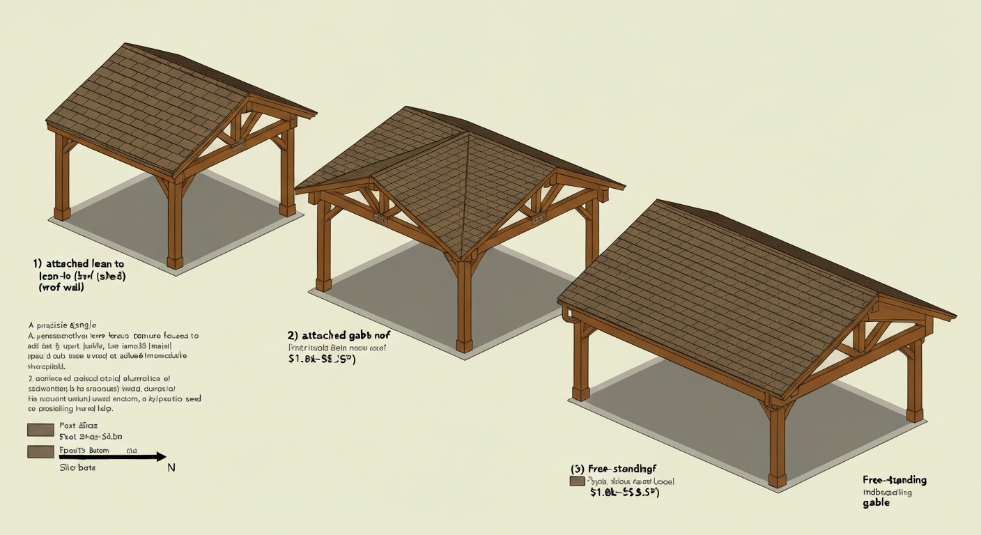
Three decisions lock in everything else: size, style, and attachment method. Make these first because they cascade into permit requirements, footing count, lumber sizing, and total cost. A rough budget range for each combination looks like this:
| Style | Typical Size Range | Attachment | DIY Material Cost (est.) | Relative Complexity |
|---|---|---|---|---|
| Lean-to (shed roof) | 10x12 to 16x20 | Attached to house | $1,800–$5,500 | Moderate |
| Gable roof | 12x16 to 20x24 | Attached or free-standing | $3,500–$12,000 | Moderate-High |
| Hip roof | 12x16 to 20x20 | Attached or free-standing | $4,000–$14,000 | High |
| Free-standing flat/shed | 10x12 to 20x20 | Free-standing posts only | $2,200–$8,000 | Moderate |
| Free-standing gable | 16x20 to 20x24 | Free-standing posts only | $4,500–$13,000 | High |
Labor costs, if you hire out any portion, typically add 40–80% on top of materials. Aluminum panel systems (sold as patio cover kits) can undercut wood-framed roofing by 20–30% and go up faster, but they limit your design options and span capability. Wood gives you the most flexibility for custom sizing and finish. Metal roofing panels over a wood or steel frame sit in the middle on cost and offer excellent longevity in wet climates.
DIY vs. hiring a pro: the honest decision matrix
Most homeowners can handle a lean-to or simple free-standing patio cover if they are comfortable with a circular saw, a drill, and basic framing. The jobs that regularly go sideways are the ones where the structural complexity, site conditions, or code requirements exceed what a first-timer can safely manage alone. Use this matrix as a gut-check before committing.
| Condition | DIY is realistic | Hire a pro or get engineering |
|---|---|---|
| Span under 14 ft, standard lumber sizes | Yes | |
| Span 14–20 ft with engineered beam | With research and inspection | |
| Span over 20 ft or multi-span structure | Yes — engineer stamp likely required | |
| Flat or low-slope site, existing concrete slab | Yes | |
| Steep slope, poor drainage, soft or expansive soil | Yes — footing design needs review | |
| High snow load zone (pg > 25 psf) | Yes — IRC R301.6 load calcs required | |
| Basic wind speed > 115 mph (ASCE 7 map) | Yes — wind uplift design needed | |
| Attached to house with simple ledger on rim joist | Yes, follow DCA-6 tables | |
| Attached to house with cantilevered or complex framing | Yes | |
| Permit required and inspector wants stamped drawings | Yes — hire a designer or engineer | |
| Working near gas, electrical, or buried utilities | Always call 811 first, may need licensed trades |
The most common mistake I see is homeowners underestimating their snow or wind zone. Pull the ASCE 7 ground snow load map for your coordinates before you finalize any beam or post sizing. If your ground snow load (pg) exceeds 25 psf, your roof framing needs to handle loads well beyond what prescriptive tables assume, and that is when a structural engineer's involvement pays for itself many times over.
Essential planning checklist
Work through this list before you spend a dollar on materials or draw a single line. Skipping items here is exactly how projects stall after the footings are poured.
- Call 811 (or your country's dig-safe number) at least 3 business days before any digging. Mark all utility locations on your site sketch.
- Measure your existing patio or target area: width, depth, distance from house, and clearance to property lines. Confirm setback requirements with your building department before designing.
- Photograph and note your existing roof line, eave height, and siding type. These details control your ledger height and flashing approach for attached designs.
- Identify your frost depth. Call your building department or check the IRC frost-depth map for your region. This sets your minimum footing depth.
- Check your local soil type using the USDA NRCS Web Soil Survey (free online tool). Identify the approximate allowable bearing capacity — most residential soils run 1,500–2,000 psf, but loose fill, organic soil, or high clay content can drop that significantly.
- Pull your jurisdiction's adopted code edition. Most U.S. jurisdictions use a version of the IRC, but the adopted year matters — 2018, 2021, and 2024 editions have different roof-load sections.
- Determine your design loads: roof live load from IRC Table R301.6, ground snow load from the ASCE 7 GIS map for your address, and basic wind speed from the ASCE 7 wind map.
- Sketch a rough plan view and elevation view. Note post locations, beam spans, rafter spans, and roof pitch. This is the drawing your building department will review.
- Set a realistic budget with a 15% contingency. Materials, permit fees, fasteners, and rental equipment add up faster than most first estimates.
- Block out your timeline: permit review (2–6 weeks is typical), material delivery lead time, and construction days. A 12x16 lean-to takes most homeowners 3–5 full working days. A 20x20 gable can take 7–12 days.
- Identify which tasks you will do yourself and which you will sub out (concrete, electrical for lighting, roofing). Get at least two quotes on subcontracted work before finalizing your budget.
- Confirm HOA approval if applicable. Some associations require architectural review before permit submission.
Site and foundation: what the ground tells you
The foundation work is where most DIY patio projects either get done right or quietly set up a future failure. The IRC Chapter 4 footing requirements (R403) are the governing reference: footings must bear on undisturbed natural soil or engineered fill, must reach below the local frost line per R403.1.4.1, and must be sized based on the allowable soil bearing pressure from IRC Table R401.4.1. In practice, for a standard patio cover with posts on 8–10 ft centers, you are typically digging to a depth of 12–48 inches depending on your frost zone, and pouring a concrete pad footing or tube-form column.
Existing concrete slab
If you already have a poured concrete patio, you have two options for post bases: core-drill and epoxy-anchor a post base into the existing slab, or set new tube-form footings adjacent to the slab edge and tie into the slab with surface-mounted hardware. Simpson Strong-Tie makes post bases (the ABU and PBS series) rated for both approaches, and their catalog gives you the allowable uplift and shear loads for each anchor configuration. What often goes wrong here: homeowners anchor into a slab that is only 3.5 inches thick or was poured without rebar, and the anchor pulls out under wind uplift. Core into the slab first to confirm thickness before specifying your anchor type.
New footings and post holes
For new post footings, dig to your frost depth, add 6 inches of compacted gravel for drainage at the bottom, and pour a concrete bell or cylindrical footing. A common prescriptive footing for a 4x4 or 6x6 post carrying a patio roof in moderate snow and wind zones is a 10-inch diameter tube form to frost depth with a 16-inch diameter belled base. In higher-load zones, go to a 12-inch tube with a 20-inch base. Use a post base hardware connector rather than embedding the post directly in concrete. Direct burial in concrete traps moisture and rots wood posts from the inside out, often within 10–15 years, even with pressure-treated lumber.
Slope and drainage
A site that slopes away from the house is actually helpful for drainage, but it creates unequal post heights. Measure each post location's grade elevation before ordering materials so you can cut posts to the correct height. For sites that slope toward the house, improve the swale and grade before building. Trapping water under a patio cover against your foundation wall is a problem no amount of flashing will fix.
Permits, code, and what inspectors actually look at
Almost every jurisdiction requires a building permit for a covered patio structure, especially when it is attached to the house. The permit process is not the enemy here. It protects you at resale (unpermitted structures can kill a home sale or require expensive retrofits), keeps your homeowner's insurance valid, and gives you a second set of eyes on the structural work. Here is what building inspectors typically check at each stage of a patio cover project:
| Inspection Stage | What the Inspector Checks |
|---|---|
| Pre-pour / footing inspection | Hole depth (below frost line), diameter, soil condition, any rebar per plan |
| Framing inspection | Post connections and hardware, beam-to-post connections, ledger attachment and fastener spacing, rafter-to-beam connections, ridge board (gable), blocking and bracing |
| Ledger / flashing inspection | Siding removal, flashing installation over WRB, fastener type and spacing per DCA-6 or plan set |
| Rough electrical (if applicable) | Any outlet or lighting circuits run to the covered area |
| Roofing / sheathing | Sheathing span rating per APA tables, nailing pattern, underlayment, drip edge installation |
| Final inspection | Overall compliance with approved plans, drainage slope, guardrails if elevation requires, address signage |
Bring your approved permit drawings to each inspection. Inspectors work faster when they can compare your work directly to an approved plan. Common code items that catch DIYers off guard: the requirement to remove siding behind a ledger (not just cut around it), the fastener spacing table for ledger lags or screws (from AWC DCA-6), and the requirement for a continuous load path from roof to footing, meaning every connection point needs rated hardware, not just toenails.
Your jurisdiction will have adopted a specific IRC edition, 2018, 2021, or 2024 are the most common in 2026. The 2024 International Residential Code, Index (IRC) shows updated roof and snow provisions (e.g., R301.6, R301.2.3 and R802.x); authors must cite the specific IRC edition adopted by their project jurisdiction 2024 International Residential Code — Index (IRC). The roof load provisions in R301.6 require that your roof framing be designed for the greater of the minimum roof live load in Table R301.6 or the ground snow load from Table R301.2 converted to a roof snow load. In practice, if you are in a low-snow zone (pg under 20 psf), the governing load is usually the 20 psf live load minimum. If you are in Denver, Minneapolis, or upstate New York, snow governs and your rafter and beam sizing will reflect that.
Choosing your style and size
The three styles that cover 95% of residential patio covers are the lean-to (single-slope shed roof), the gable (peaked ridge with two slopes), and the free-standing structure (any roof style on four or more independent posts). Each has real trade-offs beyond just how it looks.
Lean-to attached cover
The lean-to is the most common first DIY cover project for good reason. It uses the house wall as one structural support, reducing the post count and simplifying framing. The ledger attaches to the house at the high end, rafters run down at a slope (minimum 1/4:12 for most roofing products, though 3:12 or steeper is better for shingles), and a beam at the outer edge of the patio carries the rafter tails. The main weakness is that you must get the ledger flashing absolutely right, because water intrusion at that wall junction is the single most common long-term failure point for attached covers. The AWC DCA-6 guide and your shingle manufacturer's flashing details (GAF, CertainTeed, Owens Corning all publish them) must be followed precisely.
Gable roof cover
A gable roof looks more architecturally integrated with the house and handles snow and rain better than a flat or low-slope lean-to. The framing is more involved: you need a ridge board or ridge beam at the peak, rafters on both sides, and either a wall or a post-and-beam structure to carry the ridge. For an attached gable, the ridge typically terminates against the house wall (requiring a proper header or ledger to carry it), or runs parallel to the house with the gable end framed against the wall. Gable framing is a step up in complexity and usually justifies a full set of drawn plans before you order materials.
Free-standing cover
A free-standing structure has no connection to the house, which simplifies flashing and eliminates ledger concerns, but it requires a complete independent post-and-beam frame. You need at least four posts for a rectangular structure, each on its own footing. Free-standing covers work well when the patio extends further from the house than a ledger attachment can reasonably span, or when you want to cover a detached area like a pool deck. The trade-off is more concrete, more hardware, and more post work.
A 20x20 patio cover design walkthrough
A 20x20 is one of the most requested sizes because it covers a standard patio table-and-chairs setup with room to move. Here is how the structure works for an attached lean-to version at this scale, in a moderate-load zone (20 psf live load, 15 psf dead load, pg under 20 psf):
- Ledger: 2x10 pressure-treated lumber, lagged to house rim joist at 16 inches on center (or per DCA-6 Table 2 for your specific load), 20 feet long
- Outer beam: doubled 2x10 or an LVL beam, carried by three 6x6 posts spaced at approximately 7-ft centers (two corners plus one mid-span), 20 feet long
- Posts: three 6x6 pressure-treated posts on tube-form footings to frost depth, connected to beam with Simpson BC6 or equivalent post caps
- Rafters: 2x8 at 24 inches on center, spanning the 20-ft depth from ledger to outer beam (a 20-ft rafter span at 20 psf live load is at the limit of a 2x8 in most species — verify with NDS span tables or use a 2x10 for margin)
- Roof sheathing: 3/4-inch OSB or plywood rated 48/24 (APA span rating), nailed per APA schedule
- Roofing: 30-year architectural shingles over ASTM D1970-compliant self-adhering ice-and-water underlayment at eaves and valleys, synthetic felt underlayment on field
- Pitch: minimum 3:12 recommended for shingles, which means the ledger sits approximately 5 feet higher than the outer beam for a 20-ft run
For a 20x20 free-standing gable version, you would add two more posts at the house-side edge (making six posts total), eliminate the ledger entirely, run a doubled beam along both long sides, and frame a ridge beam at the center peak. The ridge beam in a 20-ft wide gable at 6:12 pitch sits about 5 feet above the top plates. Sizing that ridge beam is the critical calculation: at a 20-ft span, you are likely looking at a 3.5x11.25 LVL or an engineer-specified steel flitch plate. This is one of those points where getting a structural engineer to stamp the beam sizing is worth the $300–$600 fee. For more detail on large-format designs, the 20x20 patio cover planning topic covers this size specifically.
Style and size comparison
| Style | Best Use Case | Pros | Cons | Minimum Roof Pitch |
|---|---|---|---|---|
| Lean-to (shed roof) | Attached to house, narrow-to-moderate depth (up to 16 ft) | Simplest framing, fewest posts, lower cost | Flashing complexity, limited depth before rafter sizing escalates | 3:12 for shingles; 1/4:12 for metal panels |
| Gable roof | Wider structures, better visual match to home | Best water shedding, architectural look, handles snow well | More framing complexity, ridge beam sizing critical | 3:12 minimum |
| Hip roof | All four sides, premium look | Excellent wind and snow performance | Most complex framing, highest cost, not typical DIY first project | 3:12 minimum |
| Free-standing flat/shed | Pool decks, detached areas | No house attachment or flashing concerns | More footings and posts, needs lateral bracing | 1/4:12 for metal; 3:12 for shingles |
| Free-standing gable | Large detached outdoor rooms | Looks like a structure, great clearance | Most complex free-standing option, ridge beam engineering often required | 3:12 minimum |
Attaching to your house vs. building free-standing: structural details
The attachment decision is the most structurally significant choice you make. Attaching to the house transfers gravity and uplift loads into the house framing, which is efficient but demands proper connection hardware, fastener schedules, and waterproofing. Free-standing structures carry all loads independently, which is simpler conceptually but requires more material and more footings.
Ledger board attachment: step-by-step
The ledger is the horizontal board that attaches to your house framing and carries one end of the rafters. Getting this connection right is non-negotiable. The AWC DCA-6 guide is the prescriptive authority here, and it is free to download. Here is the sequence:
- Locate the house rim joist or band joist behind the siding. Use a stud finder and verify with a small exploratory hole. The ledger must attach to structural lumber, not to sheathing or foam alone.
- Snap a level chalk line at your ledger height. The ledger top should sit below the interior floor/deck surface or below the door threshold by at least 1 inch to prevent water from running back into the house.
- Remove all siding, foam sheathing, and housewrap in the ledger zone. You cannot flash properly over siding. The flashing must contact the structural sheathing and be integrated into the wall's water-resistive barrier (WRB).
- Install a self-adhering flashing tape (ASTM D1970 compliant) along the back of the ledger zone, lapping up the wall sheathing by 3–4 inches and folding down over the top of where the ledger will sit. This is your primary water barrier.
- Set the ledger (minimum 2x8 pressure-treated for most spans, 2x10 for spans over 12 ft) against the structural wall and fasten with 1/2-inch diameter lag screws or structural screws (Simpson SDWS or LedgerLOK are ICC-ES evaluated options) per the DCA-6 Table 2 spacing schedule. For a 12 ft rafter span at 24 inches on center, DCA-6 prescribes approximately 18-inch spacing for 1/2-inch lags in a two-row pattern.
- Install a sloped metal ledger flashing cap over the top edge of the ledger, sliding the back leg up under the WRB or housewrap. The flashing directs water away from the wall face and over the face of the ledger. Your shingle manufacturer's flashing instructions (GAF, CertainTeed, Owens Corning each publish this detail) specify the minimum flashing dimensions.
- Install step flashing at any wall-to-roof transitions beside the structure, weaving each piece with the shingle courses per the manufacturer's instructions.
- Do not reinstall siding tight to the ledger flashing. Maintain a visible flashing reveal and keep siding ends at least 1 inch above the roofing surface.
Beam and post connections for attached structures
The outer beam for an attached cover sits on posts and carries the outer rafter ends. Posts connect to footings with code-rated post base hardware (Simpson ABA, ABU, or PBS series for standard post sizes). Beams connect to post tops with post cap hardware (Simpson BC or LPC series). Never rely on toenails alone for beam-to-post connections. The uplift forces on a patio roof during a wind event can easily exceed what toenails can hold, and that failure mode is sudden. Use hardware with published uplift and shear ratings from the Simpson catalog, and match the hardware capacity to your calculated uplift load (or the prescriptive minimum your inspector requires). Simpson Strong‑Tie Fastening Systems catalog documents allowable shear/tension for SDWS and other structural screws in ledger applications and provides tested spacing/edge‑distance/stack‑up conditions, use the specific screw model’s ICC‑ES evaluation and Simpson fastener catalog as the installation authority Simpson Strong‑Tie — Fastening Systems Catalog / Technical Supplement (SDWS and ledger fasteners) documents allowable shear and tension for SDWS and other structural screws in ledger applications and provides tested spacing, edge‑distance, and stack‑up conditions; use the specific screw model’s ICC‑ES evaluation and the Simpson catalog as the installation authority..
Rafter-to-beam and rafter-to-ledger connections
Each rafter needs a hurricane tie or rafter-to-plate connector at both the ledger end and the beam end. Simpson H2.5A or H10 ties are the most common for this application. Nail them with the specified 10d or 16d nails per the connector schedule, not whatever length is handy. Using the wrong fastener (too short, too few) voids the rated capacity and the inspector will flag it. Common mistake: people install the ties correctly but use drywall screws or undersized nails to save time. Use the specified structural nails.
Free-standing post-and-beam structural sequence
- Set and plumb all post-base hardware on cured footings before erecting any posts. Measure diagonals to confirm your post layout is square.
- Cut posts to height. For a free-standing structure, all posts must be level at the top or cut to a consistent height if the site slopes. Use a builder's level or laser level to establish your reference elevation before cutting.
- Set posts in base hardware, plumb in two directions with a level, and brace temporarily with 2x4 diagonal braces staked to the ground.
- Lift the beam into post caps. For spans over 14 feet, plan your beam lift carefully — a doubled 2x10 at 16 feet weighs 130–150 lbs and needs at least two people and a temporary support post or beam cradle.
- Nail post caps and base hardware per the Simpson fastener schedule before removing any temporary bracing.
- Install permanent knee braces or diagonal bracing if required by your plan or by local code for lateral stability. A simple patio cover without knee bracing can rack in wind, especially before the roof sheathing ties everything together.
- Frame rafters, install sheathing, and roof per the sequence in the next section.
Waterproofing and flashing for both methods
For an attached cover, the flashing sequence at the ledger-to-wall junction is your most critical waterproofing work. The rule is: water must never be able to travel behind the ledger flashing and into the wall assembly. Self-adhering modified bitumen flashing tape (ASTM D1970) behind the ledger, a metal cap flashing over the ledger top, and step flashing at side walls form a complete system. Each piece must lap the one below it, not the other way around. For a free-standing cover, waterproofing is simpler: eave drip edge, felt or synthetic underlayment on the sheathing, and roofing material lapped per manufacturer instructions. There is no wall junction to worry about, but you still want to direct water away from any adjacent concrete or hardscape with adequate overhang (minimum 12 inches on each side is a practical rule of thumb).
Materials, tools, and a realistic cost breakdown
The three main structural material paths for a DIY covered patio are wood framing, aluminum panel systems, and metal roofing over a wood or steel frame. Here is an honest comparison:
| Material System | Typical Cost per Sq Ft (materials) | Lifespan | DIY Ease | Best For |
|---|---|---|---|---|
| Pressure-treated wood frame + shingles | $15–$30 | 25–40 years | High — familiar tools | Custom sizes, attached designs, traditional look |
| Pressure-treated wood frame + metal roofing | $18–$35 | 40+ years | High — lighter than shingles | Wet climates, steep or low-slope roofs |
| Aluminum patio cover kit (panel system) | $12–$22 | 20–35 years | Medium — kit assembly, limited cuts | Standard sizes, fast install, minimal maintenance |
| Steel framing + metal roofing | $22–$45 | 40+ years | Low — welding or specialized fasteners | Commercial-grade or high-wind zones |
| Cedar or redwood frame + shingles | $25–$50 | 30–50 years | High — same tools as PT wood | Premium aesthetic, naturally rot-resistant |
For a first-time builder, pressure-treated lumber with metal roofing is the combination I recommend most often. It uses standard carpentry tools, the metal panels go up quickly, and the finished product handles weather well across most U.S. climates. Aluminum kit systems are attractive for speed but limit you to manufacturer-specified spans and configurations, which may not match your site.
Basic tool list
- Circular saw (7-1/4 inch blade) for framing cuts
- Miter saw or compound miter saw for clean rafter-end cuts and trim
- Drill-driver and impact driver (separate tools make the job much faster)
- Post-hole digger or rented auger (power auger for anything deeper than 24 inches)
- Builder's level or laser level for post heights and ledger elevation
- Speed square and combination square for rafter layout
- Chalk line and tape measure (25 ft minimum)
- Hammer for framing nails and hurricane ties
- Pry bar and reciprocating saw for siding removal at ledger zone
- Caulking gun for flashing sealant
- Safety gear: safety glasses, hearing protection, work gloves, hard hat for beam lifts
- Ladder rated for your eave height (Type I or IA for roofing work)
Step-by-step framing and roofing sequence
Regardless of which style you are building, the construction sequence follows the same logic: foundation first, then posts, then beams, then rafters, then sheathing, then roofing and trim. Skipping ahead or trying to do roofing before the framing is fully braced is how people get hurt.
- Excavate and pour footings. Allow concrete to cure for a minimum of 3 days (full 28-day cure strength is ideal before loading, but 3–7 days is typical for residential timelines with normal-weight concrete at standard temps).
- Set and plumb posts. Install temporary bracing. Do not remove bracing until beams and at least the first rafter are in place.
- Install ledger (attached designs only). Complete all flashing work before proceeding. Get ledger inspection if your jurisdiction requires it at this stage.
- Install outer beam(s). Connect to post tops with rated post cap hardware. Confirm beam is level and square to the ledger.
- Lay out and cut rafters. Mark rafter locations on both ledger and beam at your specified on-center spacing (16 inches or 24 inches per your plan). Cut the bird's mouth (the notch where the rafter seats on the beam) carefully — too deep weakens the rafter, too shallow and it rocks.
- Install rafters and hurricane ties at every bearing point. Do not skip ties at any location.
- Install roof sheathing. Use APA-rated panels at the span rating specified in your plan (commonly 32/16 for 24-inch rafter spacing). Nail with 8d common nails at 6 inches on-center at edges and 12 inches in the field, or per your local code nailing schedule.
- Install drip edge along eaves before underlayment, then underlayment, then drip edge along rakes over underlayment (this is the correct sequence).
- Install self-adhering ice-and-water underlayment (ASTM D1970) at eaves (minimum 24 inches past the interior wall line in snow-country), in valleys, and around any penetrations.
- Install field underlayment (synthetic felt) over the remaining sheathing, lapped 4 inches at horizontal seams and 6 inches at vertical seams.
- Install roofing material per manufacturer instructions. For shingles: start at the eave, offset joints between courses, nail with roofing nails at the manufacturer's specified nailing line. For metal panels: follow the panel manufacturer's lap and fastener schedule exactly, including the required exposed-fastener washered screws or concealed clip system.
- Install ridge cap, hip cap, or ridge vent as specified.
- Install fascia, soffit, and trim. These are finish elements but also functional: they protect rafter tails from water and pests.
- Schedule and pass final inspection.
Safety practices worth taking seriously
Falls are the leading cause of DIY construction injuries, and patio roof work involves ladders, elevated framing, and carrying awkward loads like beams and sheathing. A few non-negotiable practices: always have a second person present during beam lifts. Set up scaffolding or a pump-jack system for any roofing work above 8 feet rather than repositioning a ladder every two minutes. Wear a fall-arrest harness if you are working on a pitched roof above 6:12. Keep your work area clear of scrap lumber and fasteners, because stepping on a nail on a job site is completely avoidable and completely common. When cutting pressure-treated lumber, wear an N95 respirator and do not burn the offcuts. PT lumber preservatives are not something you want to inhale or leave in a fire pit.
Drawing your plans: what to put on paper
Most building departments require a minimum of a site plan, a floor/foundation plan, and at least one elevation view, plus a materials and structural notes sheet. You do not need CAD software for a simple patio cover. A clean hand-drawn set on graph paper at a consistent scale (1/4 inch equals 1 foot is standard for residential structures) will satisfy most plan reviewers for straightforward projects. Your plan set should show: overall dimensions, post and footing locations with sizes and depths, beam sizes and species, rafter size and spacing, roof pitch, sheathing specification, ledger attachment detail with fastener type and spacing, all connector hardware called out by model number, and a note referencing your design loads (live load, dead load, snow load if applicable). If you want detailed guidance on turning field measurements into a complete dimensioned drawing, the topic on how to draw patio cover plans covers that process specifically. For step-by-step drawing instructions, see how to draw patio cover plans (topic ID 24f83a83-239f-4059-a6c0-7550fdd3d152). For step-by-step instructions on building one yourself, see our how to build backyard patio cover guide.
Finishing options: roofing, trim, and lighting
Once the structure passes inspection, the finishing work is what makes it feel like a real outdoor room rather than a construction site. For ideas on high-end materials, lighting, and detailing, see a guide on how to build a luxury patio cover. For roofing, architectural (dimensional) shingles give the best weather resistance and curb appeal for a wood-framed attached cover. Standing-seam metal roofing is the premium choice for longevity and low maintenance. Corrugated or ribbed metal panels are the budget-friendly option and install quickly. Clear or translucent polycarbonate panels work well for free-standing covers where you want to keep natural light, they let through 80–90% of daylight while blocking UV and rain. For trim, primed and painted pine or composite fascia boards are the workhorses. Cedar or Azek (PVC trim) are worth the upside cost in high-humidity climates where painted pine will need attention every 5–7 years. For lighting, adding a single exterior-rated junction box and conduit run during framing costs almost nothing and saves significant work later if you want a ceiling fan or pendant light. Run the conduit before the sheathing goes on and cap it at the box location during framing inspection.
When to stop and call a professional
Even well-prepared DIY builders hit moments where the right call is to pause and get professional input. If your footing excavation hits water, soft organic material, or very loose soil at depth, stop and call a geotechnical engineer or a foundation contractor before pouring concrete. If your plan reviewer sends back a correction requiring engineered drawings, that is not a rejection of your project, it is a request for documentation. A structural engineer who does residential work can stamp a simple patio cover plan for $300–$800 in most markets and that fee often pays for itself in material savings from properly sized beams. If you discover that the existing rim joist you planned to attach your ledger to is rotted or undersized, do not work around it. Fix the house framing first. Attaching a ledger to compromised framing transfers the structural problem to your patio cover and creates a safety risk. Building a covered patio off your house in particular requires that the house structure is sound at the attachment point, and that is worth a careful look before you start.
FAQ
What primary codes and standards must be cited to make publication‑ready covered patio plans authoritative and code‑compliant?
Cite the edition adopted by the project jurisdiction. Minimum authoritative references: International Residential Code (IRC) — relevant sections R301 (loads), R401/R403 (foundations/footings), R802 (roof framing) for the chosen year (2021/2024 or locally adopted edition); ASCE 7 (current adopted edition, e.g., ASCE 7‑16 or 7‑22) for wind and snow load procedures and maps; AWC National Design Specification (NDS) and NDS Supplement for lumber design values and adjustment factors; AWC DCA‑6 prescriptive deck/ledger guidance for ledger attachments; APA panel span ratings for roof sheathing; Simpson Strong‑Tie (or equivalent) manufacturer catalogs/ICC‑ES reports for fasteners, connectors and ledger screws; ASTM D1970 for self‑adhering underlayment; and major roofing manufacturer installation/flashings (GAF/CertainTeed/Owens Corning) for compatible flashing details.
What load and climate inputs are needed to size rafters, beams and connections?
Specify site latitude/coordinates and use: ASCE 7 ground snow load (pg) or local ground‑snow map (ASCE GIS) to determine roof snow loads per ASCE procedures; local basic wind speed and exposure category per ASCE 7; IRC prescribed roof live load (Table R301.6) where applicable; roof dead load (sheathing, roofing, framing weights); and seismic design category if applicable per IRC/ASCE. Convert pg to roof snow load using ASCE 7 methods and determine controlling load case (snow vs wind vs live).
What geotechnical and foundation data must be provided for footings and posts?
Include soil type and allowable bearing capacity from USDA NRCS/SSURGO or a local geotechnical report; local frost depth or code frost‑protection requirement; groundwater table if present; footing minimum dimensions per IRC Chapter 4 (R401/R403) and local amendments; recommended footing types (cast‑in‑place concrete pads, piers, frost‑protected shallow foundations) with minimum concrete strength (e.g., 2,500–3,000 psi typical) and rebar or anchor bolt details when required; and site excavation and compaction notes (compaction spec % and lift thickness) if building over fill.
What prescriptive member sizes and span references should be listed for wood (20x20 example)?
Provide a prescriptive span table citation (APA/IRC/NDS) and an example schedule rather than a universal prescription. For a typical 20x20 lean‑to or gable patio with common southern yellow pine or Douglas‑fir and roof loads within moderate snow/wind: rafter spacing 16" o.c. with 2x8 or 2x10 rafters depending on span and loads; ridge/hip/beam sizing per span tables (example: a single 20' clear span free‑bearing beam often requires double LVL or glulam (e.g., two 1‑3/4" x 9‑1/2" LVLs) or built‑up 3‑ply 2x10/2x12 depending on loads — verify with NDS/engineering); post spacing typically 8'–10' max for wood beams with appropriate beam depth; ledger sizing per DCA‑6 with specified fasteners/spacing. Always state that final member sizes must be checked to local loads using NDS and APA/span tables and include a sample calculation reference.
What manufacturer and product specs are required for ledger and connector details?
Include manufacturer model numbers and ICC‑ES evaluation report references for structural screws/fasteners (e.g., Simpson LedgerLOK, SDWS, Strong‑Drive SDWH; provide catalog load tables and required embedment/edge distances). Specify connector types (post bases, beam hangers, hurricane ties) with catalog numbers and allowable loads. Provide fastener sizes, spacing, and installation notes per the manufacturer instructions and DCA‑6 (e.g., 1/2" lag/bolt spacing table alternatives and required pre‑drilling where applicable). Include corrosion class (hot‑dip galvanized or stainless) when used with treated lumber or coastal exposure and cite the connector manufacturer corrosion guidance.
What dimensioning, drawing sheets and notes are required for a publication‑ready plan set?
Minimum drawing package: site plan with property line, house elevation, patio footprint, setbacks and grade; foundation plan with footing sizes, depths, post locations and reinforcing; plan view with post/beam/rafter layout, member sizes and spacings; roof framing plan with rafter layout, ridge/valley locations, gutters, slopes and overhangs; elevations (front/side) and detail sheets for ledger attachment, post‑to‑footing connection, beam splice, flashing, and roof/wall intersection. Each drawing must include a title block, scale, north arrow, keynotes legend, general notes referencing code edition, design loads (snow, wind), material specifications, and a bill of materials. Provide dimensioned 20x20 example set (floor plan, beam/post locations at 8' centers, footing sizes called out).