To draw usable patio cover plans, you need four things on paper: a site plan showing where the cover sits on your property, a layout plan with all dimensions, a roof plan showing slope and framing, and at least one elevation drawing showing post heights, beam positions, and overhangs. Get those four drawings right and you have something you can build from and, in most jurisdictions, submit for a permit.
How to Draw Patio Cover Plans for a Buildable Design

Celia Vaughn
28 Jun 2026

Clarify your patio cover design goals and constraints first
Before you draw a single line, spend 20 minutes answering a few questions because the answers change what goes on paper. First: is this a permanent roofed structure attached to your house, or a freestanding shade structure? Most building departments define a patio cover as a one-story roofed structure no more than 12 feet above grade, used for outdoor living. That definition matters because it puts your project under a specific permit pathway with specific structural rules.
Next, figure out your non-negotiables. What size do you actually need? If you're covering a 16x20 concrete slab, you probably want a structure close to that footprint. Will you attach it to the house or go freestanding? Attached covers share a ledger with the house wall, which simplifies some framing but adds complexity around waterproofing and attachment hardware. Freestanding covers need posts on all four sides and their own independent footings. Knowing this upfront saves you from redrawing everything later.
Also think about materials now, not after you draw. Wood (typically Douglas Fir or Southern Yellow Pine) is the most DIY-friendly to design for and source locally. Aluminum kit systems come with their own span tables and connection hardware, so you're often working from a manufacturer's pre-engineered plan template. Steel is less common for DIY but shows up in larger or heavier builds. The material choice affects every dimension on your plan: lumber span tables are different from aluminum extrusion span tables, and your drawings need to reflect whichever system you're using.
Gather measurements and site information before you draw anything

Accurate drawings start with accurate field measurements. This is where a lot of DIY plans fall apart. People sketch dimensions from memory and end up with a plan that doesn't match the actual house wall or slab. Go outside with a 25-foot tape measure, a notepad, and a helper if you can get one.
Here's what you need to record. Measure the exact width and depth of the area you want to cover. Measure the height of the house wall at the point where a ledger or beam would attach. If you're attaching to the house, find and mark the rim joist or wall framing location behind the siding because that's where your ledger goes. Measure from the finished floor or slab level to the eave line of the existing roof to understand how much vertical clearance you're working with. Also measure the distance from the house wall to any property lines, because setback requirements in your jurisdiction will directly limit how far out your cover can extend.
While you're out there, note a few site facts your drawings will need: which direction the house faces (this affects where you want drainage to run), whether the ground is level or sloped under the proposed cover area, and whether there are any utilities (electrical, gas, or irrigation lines) running under the slab or soil nearby. If you're pouring new footings, you'll need to know what's underground.
- Overall width and depth of the covered area (measure to the nearest 1/4 inch)
- House wall height at the attachment or reference point
- Rim joist or stud framing location behind siding for ledger attachment
- Distance from house to nearest property line (both sides and rear)
- Finished slab or ground elevation relative to the house floor level
- Location of any existing downspouts, windows, doors, or electrical outlets on the wall
- Soil type or existing footing information if visible
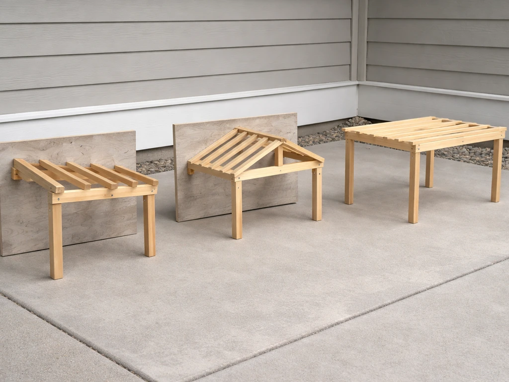
Choose your patio cover style and framing approach
The three main styles are a lean-to (also called a shed-roof), a gable roof, and a freestanding flat or gable structure. Each one produces a different set of drawings and different structural demands. Pick the one that fits your site and skill level before you start laying out dimensions.
Lean-to (shed-roof) covers
A lean-to is the most common attached patio cover and the easiest to draw and build. If you are building a covered patio off your house, make sure this attached style matches your site and your attachment and waterproofing details attached patio cover. The roof slopes in one direction, typically away from the house. The high side attaches to the house via a ledger board, and the low side is supported by posts and a beam (sometimes called a header or rafter plate). Because the structure is simple, the drawings are simpler too: you need a layout plan, one roof plan, and two elevations (a side elevation and a front elevation). This is the style I'd recommend for most first-time DIY plan-drawers.
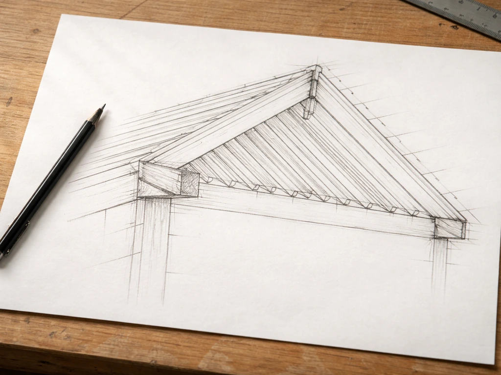
Gable roof covers
A gable cover has a peaked roof with two slopes. When attached to the house, one end of the gable typically ties into the house wall. Gable structures look more substantial and shed water in two directions, which helps on wider covers. The drawing set gets more complex: you need a layout plan, a roof framing plan showing ridge beam placement and rafter layout, and at least three elevations (front, side, and rear). You'll also need a ridge beam size calculation, which means consulting a span table or getting an engineer to check your numbers.
Freestanding covers
Freestanding structures don't attach to the house at all. They need posts at all four corners (and sometimes in between, depending on span), their own beams on all sides, and footings under every post. On paper, this means your layout plan shows a complete independent structure, and your elevations need to show all four sides. Freestanding designs give you more placement flexibility but require more footing work and more structural planning. If you're thinking about a 20x20 freestanding cover, the span and load math becomes critical and you'll want to cross-check against a proper span table or have an engineer review the plan.
| Style | Attachment | Drawings needed | Structural complexity | Best for |
|---|---|---|---|---|
| Lean-to (shed-roof) | Attached to house via ledger | Layout, roof plan, 2 elevations | Low | Most attached DIY covers, first-time plan drawers |
| Gable roof | Attached or freestanding | Layout, roof framing plan, 3+ elevations | Medium-High | Wider covers, better aesthetics, heavier rainfall areas |
| Freestanding flat or gable | No house attachment | Layout, roof plan, 4 elevations, footing plan | Medium-High | Detached patios, poolside, structures away from house |
Convert your measurements into plan drawings
You don't need CAD software to draw workable plans. A pencil, a ruler, graph paper (1/4-inch grid is ideal), and a scale of 1/4 inch = 1 foot works well for most patio covers. At that scale, a 16-foot-wide structure is 4 inches wide on paper, which is easy to dimension clearly. If you prefer digital tools, free programs like SketchUp Free or even Google Slides let you draw to scale without paying for anything.
Start with the layout (floor plan) drawing
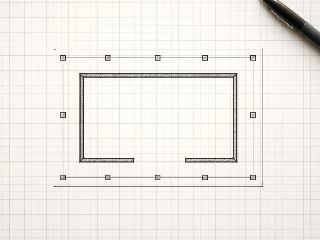
Draw the footprint of the structure as seen from above. Show the house wall as a thick line, the outer edge of the cover as another line, and mark the post locations as solid squares or circles. Dimension the overall width and depth, plus the spacing between posts. Mark the ledger location on the house wall. Include the existing slab or patio edge if it's relevant to the layout. This drawing tells a builder (or inspector) where everything sits in relation to the house and property.
Draw the roof plan
The roof plan is the layout drawing but focused on the framing above. Show the ledger or ridge beam, the rafter direction (draw them as parallel lines spanning from the ledger to the outer beam), and mark the rafter spacing (typically 16 or 24 inches on center). Show overhangs at the eave and rake ends. Mark the roof slope as a pitch notation (for example, 2:12 means 2 inches of rise for every 12 inches of run). Label every member: ledger, beam, rafter, and any blocking.
Draw the elevations
An elevation is what the structure looks like from the side or front, flattened into a 2D view. For a lean-to, draw the side elevation first: show the house wall on the left, the ledger at the top of the wall, the sloping roof line going down to the outer beam, and the post supporting the beam at the far end. Dimension the post height, the ledger height, and the roof slope. Then draw the front elevation: show the two posts (or however many), the beam across the top, and the roof edge. Dimension the beam height and overall width. These two drawings together tell a framer exactly what the structure looks like in 3D.
A common mistake here is forgetting to show dimensions in both directions on every drawing. Every member needs a size label (like '2x8 rafter' or '4x6 post') and every space needs a dimension. Permit reviewers will send your plans back if members aren't labeled with species and size, and you'll be frustrated during construction if you have to guess.
Structural considerations you need to account for in DIY plans
This is the section that separates plans you can actually build safely from plans that just look good on paper. Under model building codes, patio covers must be designed to handle dead loads (the weight of the structure itself) plus a minimum vertical live load of 10 pounds per square foot (psf). The 2015 IRC Appendix H also treats patio covers as needing dead load plus a minimum 10 psf vertical live load, with greater snow loads where applicable. If you're in a snow climate, design snow loads replace that 10 psf minimum wherever snow loads are higher. The structure also has to resist wind and seismic loads, which your local building department will have specific values for.
For a wood-framed lean-to with a lightweight polycarbonate or aluminum panel roof, 10 psf is typically achievable with standard lumber sizes. For heavier roofing like composite shingles or concrete tile, you're adding dead load on top of that 10 psf live load, and your beams and posts need to be sized accordingly. Use the span tables in the IRC (International Residential Code) or your local code to verify that your chosen rafter size can span the distance you're planning at the spacing you've drawn. If you're figuring out how to build a covered patio yourself, use these span table checks before you commit to rafter sizes and spacing span tables. Don't just pick a rafter size because it looks right.
Posts and beams
For most residential patio covers, 4x4 posts work for heights up to about 8 feet with moderate spans. For taller structures or longer beam spans, step up to 4x6 or 6x6 posts. Beams (the horizontal members carrying the rafters at the outer edge) need to be sized for the span between posts and the tributary area of roof they're supporting. A beam spanning 10 feet with rafters framing into it every 16 inches carries a lot more load than one spanning 6 feet, and the plan needs to show the right size for the right span. Your drawings should call out beam size, species (Douglas Fir, Southern Yellow Pine, etc.), and the connection method at each post.
Ledger attachment (for attached covers)

The ledger is where attached patio covers often fail, both structurally and in permit review. Your plans must show a ledger detail: a close-up drawing showing the ledger board size, the fastener type and spacing (typically structural lag screws or through-bolts into the rim joist), and how water is kept out (flashing over the top of the ledger). Reviewers want to see this detail specifically because improper ledger attachment is a documented failure point. Draw it at a larger scale, like 1 inch = 1 foot, so the fastener pattern and flashing are clearly visible.
Footings
Every post needs a footing, and your plans need to show footing size and depth. Footing depth depends on your local frost depth, which your building department can tell you. A common residential patio cover footing is a concrete caisson (a round drilled hole) 10 to 12 inches in diameter and deep enough to get below frost line. Your plan should show a footing detail with diameter, depth, and how the post connects to the concrete (a post base hardware detail is standard).
Drafting the roof plan and elevations in detail
Roof slope (pitch) is one of the most important things your drawings need to specify, and it's often the thing DIY plans get vague about. A lean-to patio cover needs at least a 1:12 pitch to drain reliably, and 2:12 is better for most roofing materials. Mark the pitch on your roof plan using a pitch triangle notation, and show it again on the side elevation. If your jurisdiction uses metric, convert: 1:12 is about an 8% slope.
On the roof framing plan, lay out every rafter at the spacing you've chosen and mark the spacing clearly (for example, '2x6 rafters at 24" o.c.'). Show the overhang distance at the eave (how far the roof extends past the outer beam) and at the rake ends if applicable. A 12-inch eave overhang is common and provides some weather protection for the posts and beam. Show any blocking at the eave end or at the ledger. If you have a gable design, show the ridge beam location and size, and show the common rafter layout from the ridge down to the top plates on each side.
On your elevations, dimension everything vertically: finished grade to top of post, top of post to bottom of beam, bottom of beam to top of rafter at the high and low ends (this shows your slope physically), and the overhang extension. Horizontal dimensions should match your layout plan exactly. If a dimension on the elevation doesn't match the layout plan, a builder will stop and ask you which one is right. Consistency across drawings is what makes a plan set actually usable on a job site.
What your plans need for materials, hardware, and permits
A buildable plan isn't just geometry. It needs to specify materials and hardware so the person building it (even if that's you) knows exactly what to buy. As a real-world example, Douglas County's permit requirements ask for the species and sizes of all lumber, the size and spacing of caisson footings, a ledger attachment detail, the type of roof covering, and complete elevation drawings. That list is a good minimum target for any jurisdiction.
On your drawings or in a separate notes sheet, call out the following for every major element: lumber species and grade, actual dimensions (a 2x8 is actually 1.5 inches by 7.25 inches, and reviewers sometimes care), fastener type and size for each connection (joist hanger, post cap, lag screw, carriage bolt), roofing material type (polycarbonate panels, metal roofing, asphalt shingles), and flashing details at the ledger and any wall intersections. Hardware like post bases, post caps, and rafter ties should be called out by the manufacturer's model number if you're using catalog hardware, because that's how inspectors verify load ratings.
For permitting, you'll typically submit your plan set (layout, roof plan, elevations, and details) along with a site plan showing the structure's location on your property relative to property lines and the house. Check your local building department's submittal checklist before you finalize drawings, because requirements vary. Some jurisdictions accept hand-drawn plans if they're neat and dimensioned. Others require CAD or PDF submittals. Call ahead and ask before spending time in the wrong format.
When to bring in a professional or engineer
Most simple lean-to patio covers in low-wind, low-snow areas can be designed and drawn entirely by a homeowner using code span tables and this kind of process. But there are situations where you should stop and get a professional involved. If your project is in a high-wind zone (coastal areas, tornado-prone regions), a high-snow-load area, or a high seismic zone, the load calculations go beyond what basic span tables cover. If you want a higher-end finish like how to build a luxury patio cover, it is especially smart to treat wind, snow, and seismic regions as a prompt to get professional review. If your beam spans are over 14 to 16 feet, a structural engineer can verify your sizing in an afternoon and the cost is usually $200 to $500, which is cheap insurance. If your building department requires stamped plans (an engineer's or architect's seal on the drawings), that's a non-negotiable: you need a licensed professional to produce or review the plans before submittal.
You can still do all your own measuring, layout, and preliminary drawings, and hand that work to an engineer for review. That approach saves money compared to starting from scratch with a professional, and it keeps you in control of the design. Many homeowners who tackle larger projects, like a 20x20 cover or a full gable structure with a heavier roof, find that approach works well.
Pulling your plan set together
When you're done, your plan set should include at minimum: a site plan (property outline, house footprint, and proposed cover location with dimensions to property lines), a layout or floor plan (footprint with post locations and all dimensions), a roof framing plan (rafter layout, spacing, slope, and overhangs), at least two elevations (typically front and side for a lean-to, or all four sides for a freestanding structure), a ledger attachment detail if the cover is attached, a footing detail, and a materials/hardware schedule. That's six to eight sheets for a typical project. It sounds like a lot, but each drawing builds on the measurements you already took, and once the layout plan is right, the rest follows logically.
If you're planning to get into more detailed construction steps after your plans are approved, the actual build process for attached and freestanding covers involves its own sequencing and technique decisions. To finish the job, you will also want to nail down the materials, footing sizes, and ledger attachment details that make a backyard patio cover safe and code-compliant how to build backyard patio cover. The planning work you do here directly feeds into that build process, so the more precise your drawings are now, the smoother the construction phase will go.
FAQ
Can I submit hand-drawn patio cover plans for a permit?
Yes, but only up to a point. If the plan set is for permit submittal, many jurisdictions require a specific drawing standard (PDF/CAD, minimum sheet sizes, legible scales, and complete member sizes). If you want to start by hand, confirm with the building department first, then keep your hand-drawn scale consistent across every sheet and include a title block with project address, scale, and page numbers.
What measurement reference should I use for post height and roof height (grade, finished floor, or slab)?
Use one elevation as the “truth” for vertical clearances and make every other drawing match it. In particular, set your dimensions from finished floor or slab to finished grade references, not raw soil or subgrade. If you show grade in one place and use a different starting point in another, reviewers may flag it because roof height, clearance, and post sizing become ambiguous.
What should my ledger detail include to avoid permit corrections?
For attached covers, treat the ledger area as a weatherproofing and attachment system, not just a board size. Include flashing that extends both directions over the ledger, show how water sheds away from the wall, and note whether siding is removed or not where the ledger bolts go. If your plan only states “ledger with bolts” but does not show water management, it often triggers a correction request.
How do I handle situations where a planned post lands on an existing utility or obstruction?
Plan for a separate footing reality check before you finalize framing sizes. If the proposed footing locations hit existing concrete, trees, or utilities, you may need to shift posts or change span strategy. Your final layout plan should be “post-compatible” with what is underground (and near it), otherwise you end up redesigning beams, rafters, and footing details after approvals.
How do I know whether my project should be treated as attached or freestanding for the plans?
A quick decision aid is: if your roof framing will carry loads into the house wall (attached) you need ledger sizing and flashing shown, if it is fully freestanding you need a complete independent structural system with post-by-post footings. For freestanding builds, do not assume you can reduce the footing count without recalculating spans, because fewer posts increases beam span and load dramatically.
What is the most common pitch-related drawing mistake, and how can I avoid it?
Choose roof pitch based on the roof covering and climate, then lock it before you draw member lengths. A common mistake is selecting a pitch that drains, but then using rafter lengths and overhangs that do not reflect that pitch. Confirm that your pitch notation on the roof plan matches the vertical drop shown on the elevation, because inconsistencies are a common reason for plan review rejection.
Do I need to show every rafter and rafter spacing if an engineer is doing the calculations?
You still need a drawing that shows how the roof loads transfer to the structure. Even if an engineer calculates loads, your plan should clearly show rafter spacing, rafter direction, which members connect at the ledger or ridge, and what end supports do. A “roof outline only” plan usually fails review because inspectors cannot verify the load path.
If I use an aluminum kit system, what changes in the way I should draw the roof framing plan?
Yes, but you must design and label the system you are proposing. If you use a kit, your drawings should either (1) reproduce the manufacturer’s plan template with the required local dimensions and site parameters, or (2) reference the kit’s engineered span tables and connection details on the sheet. Never mix lumber sizes, connection hardware, or span assumptions from different systems without updating the drawings.
How specific do the lumber species and sizes need to be on my drawings?
For permitting, call out actual post, beam, and rafter sizes as used in the design, along with species (and grade if required). Reviewers may also want the connection hardware type and fastening pattern. If you only write “2x lumber,” you can end up with a correction even when the concept is right, because species and connection details drive allowable loads.
What should go into the materials and hardware schedule so the reviewer can approve without back-and-forth?
A good rule is to list every item that affects structural capacity and water control: ledger flashing, post bases, post caps, rafter ties, beam-to-post connections, and the roof covering type. Roofing weight matters, so specify the roof covering material and, if known, its rated weight. For wiring or ceiling fans, show clearances and any required blocking, but keep the structural schedule separate from electrical if your jurisdiction expects different review tracks.