
Patio tube brackets are the metal connectors that join hollow structural tubes (round or square) to posts, beams, walls, or concrete footings in patio covers, pergolas, and shade structures. You slide or bolt the tube into or onto the bracket, fasten it down, and the bracket transfers the load to whatever it is attached to. Get the right bracket for your material, size it for the load, install it with the correct fasteners and torque, and your frame will stand safely for decades. Get those things wrong and the whole structure is at risk. This article walks through every step: selection, layout, tools, fasteners, installation for both attached lean-to and freestanding builds, flashing, corrosion protection, and what to watch for when things do not go to plan.
How to Use Patio Tube Brackets: Select, Install & Maintain

What patio tube brackets are and when you need them
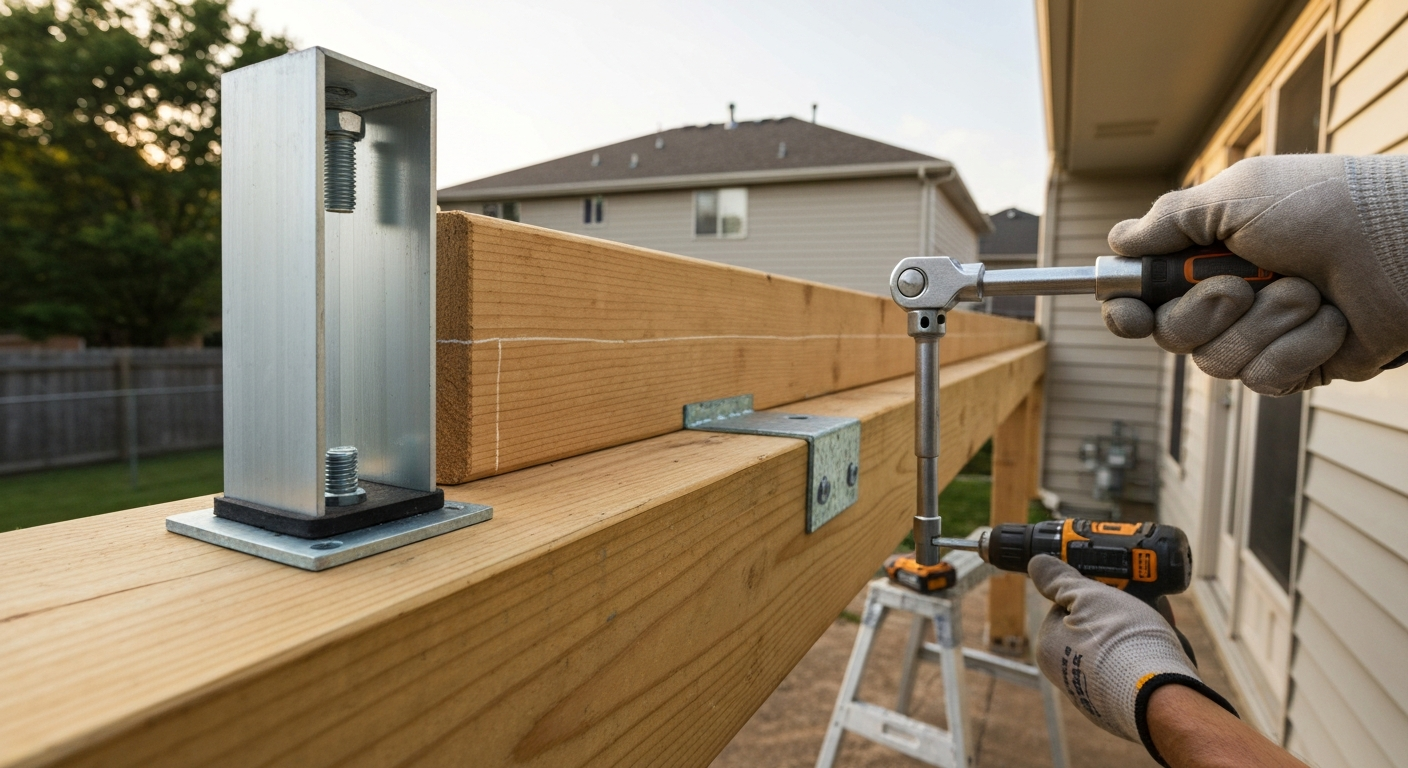
A tube bracket (also called a tube connector, post-to-beam connector, or structural tube fitting) is a metal fitting designed to receive a hollow structural section (HSS) or extruded tube and mechanically connect it to another structural member or surface. In patio cover work, you encounter them at four main connection points: post bases (tube-to-concrete), post-to-beam connections (tube column meeting a horizontal tube beam), beam-to-wall ledger connections (the point where an attached patio roof meets your house), and rafter or purlin end connections (horizontal tube members sitting on a beam). They are not optional hardware. Without a proper bracket, you are relying on friction, gravity, or a few poorly loaded screws to hold the frame together, which is not a structure, it is a liability.
Common use-cases where tube brackets show up in DIY patio projects include: aluminum pergola kits with square extruded tube columns; attached lean-to patio roofs using rectangular steel or aluminum tube rafters bolted to a wall ledger; freestanding shade structures with round steel posts set into surface-mounted post bases; and hybrid wood-and-metal builds where a steel tube purlin spans between wood beams. If your project involves any hollow structural tube (as opposed to solid lumber), you will need brackets engineered for that tube profile.
Choosing the right bracket: load, span, and material compatibility
The single most important thing to understand before you buy any bracket is that connectors are load-rated, and you have to match the rating to your actual structural demand. The International Residential Code Appendix AH, which covers patio covers specifically, requires design for dead load plus a minimum 10 psf (pounds per square foot) vertical live load, plus wind loads per your local jurisdiction as defined by ASCE 7. Snow load replaces the 10 psf minimum wherever applicable. That sounds technical, but for most DIY patio covers in mild climates with spans under 12 ft and no snow, a simple tributary area calculation gives you the load each bracket must carry. Multiply your tributary area (in square feet) by the total design load (typically 20 to 30 psf for a simple patio cover in a low-snow, moderate-wind zone) and you have the bracket's required capacity in pounds. Compare that against the manufacturer's allowable load table for the specific bracket model.
Simpson Strong-Tie publishes allowable-load tables in their Wood Construction Connectors catalog for every connector in their lineup, including the APVB adjustable post bases and the Outdoor Accents series. See the Simpson technical data sheet blank" rel="noopener noreferrer">Technical data sheet PBP60/50 Post Base | Simpson Strong‑Tie for dimensional data, typical installation notes, and model-specific bolt patterns and allowable uses, always follow the product data sheet for exact fastener schedules and limitations. Those tables list both uplift (tension) and lateral (shear) capacity for each fastener schedule. Always use the table values for the specific bracket model, not a generic number from a blog post or YouTube video. Hilti's Anchor Fastening Technical Guide does the same for concrete anchors. See the blank" rel="noopener noreferrer">Hilti Anchor Fastening Technical Guide (embedment, concrete/CMU tables) for specific anchor capacity tables, worked examples, and installation requirements that govern anchor selection and design. These documents are free to download and are the authoritative source for what a given product can actually hold.
Matching brackets to your frame material
| Frame Material | Recommended Bracket Material | Key Compatibility Notes | Typical Finish |
|---|---|---|---|
| Aluminum tube (6063 or 6061 extrusion) | Aluminum alloy bracket or hot-dip galvanized steel with isolation tape/washer | Bare steel touching aluminum causes galvanic corrosion; isolate metals or use aluminum-to-aluminum connectors | Clear anodized or powder-coated |
| Steel HSS tube (square or round) | Hot-dip galvanized steel (ASTM A123/A153) or zinc-plated heavy-duty bracket | Match tube wall thickness to bracket throat depth; HDG coating resists outdoor exposure | Hot-dip galvanized |
| Pressure-treated wood post with tube beam | G185 galvanized or stainless steel (ACQ-rated) | ACQ/CA-treated lumber corrodes standard zinc; use Simpson Strong-Tie ZMAX or stainless hardware | ZMAX or stainless |
| Wood beam with steel or aluminum tube rafter | Joist/rafter hanger rated for tube profile width | Confirm hanger throat width matches tube face dimension exactly; shim if needed | G185 galvanized or powder-coat |
One detail that catches a lot of first-timers: if you are mixing aluminum tube with any steel hardware, you must use a dielectric barrier (neoprene washer, isolating tape, or a polymer-sleeved bolt) at every metal-to-metal contact point. Skip that and you will have white powder and pitting corrosion at every joint within two or three rainy seasons.
Bracket types and mounting options
Wall-mounted (ledger attachment) brackets
For an attached lean-to patio cover, the beam or rafter ends connect to a ledger board or directly to a wall-mounted bracket anchored into your house framing. The bracket must transmit both vertical load (the weight of the roof plus anything on it) and lateral load (wind trying to pull the structure away from or into the wall). Anchor into house framing studs or rim joist, not just sheathing. Lag screws into studs are the most common DIY-accessible option: 1/2-inch diameter, minimum 3-inch embedment into solid framing, with a flat washer under the head. Through-bolts (carriage bolt or hex bolt with nut and washer on the inside) are stronger and preferred where you can access the interior wall.
Post-to-beam brackets
These sit at the top of a column post (tube or wood) and cradle or cap the beam. Simpson APVB adjustable post bases (used inverted as post caps in some configurations) and dedicated post cap connectors like the BC/BCS series are designed exactly for this. The bracket wraps the top of the post, and the beam drops into the saddle. You fasten both sides with the specified Strong-Drive screws or bolts from the product's data sheet. Do not substitute hardware or skip fastener holes. Every hole in a connector is there for a reason.
Post base brackets (post-to-concrete or post-to-deck)
Post bases transfer column loads into a concrete footing, slab, or deck. The Simpson APVB adjustable post base is one of the most widely used DIY-accessible products: it arrives as a two-part assembly (standoff plate plus adjustable post holder), and you anchor the base plate to concrete with specified wedge or adhesive anchors before setting the column. Current retailer listings (see Home Depot, Simpson Strong‑Tie post bases (retail pricing and SKU listings)) show typical retail prices for APVB44 around $27–$55, FPBB44 about $32, and adjustable/spike bases in the ~$15–$40 range, varying by nominal post size and finish Home Depot — Simpson Strong‑Tie post bases (retail pricing and SKU listings). The standoff lifts the post end off the concrete surface, which dramatically reduces moisture contact and rot or corrosion at the base. For freestanding structures on a concrete patio slab, surface-mounted post bases are common. For a new pour, cast-in-place anchor bolts give the strongest connection.
Freestanding tube frame connectors
A freestanding pergola or shade sail structure uses tube-to-tube connectors (inline splices, 90-degree corner fittings, T-fittings, and cross fittings) in addition to post bases. Aluminum kit systems often include proprietary snap-in or set-screw fittings sized for their specific tube profile. Non-kit builds using steel HSS typically weld corners or use bolted gusset plates. For DIY non-welded steel or aluminum tube frames, look for mechanical tube fittings from structural fitting suppliers that specify tube wall thickness and allowable load, not just the tube outside diameter.
Materials and shopping checklist
Before your first hardware store trip, make a complete list organized by connection type. Showing up with a bracket but the wrong anchor diameter wastes a whole day. Here is a practical checklist covering a typical attached patio cover build.
- Tube brackets: post base connectors, post cap/beam connectors, rafter hangers (quantity per your layout, plus 10% extra)
- Lag screws: 1/2-inch diameter, 3.5- to 4-inch length for ledger-to-framing connections; hex head for socket wrench access
- Through-bolts: 1/2-inch carriage or hex bolts with matching nuts and SAE flat washers for beam-to-post connections
- Concrete wedge anchors: typically 1/2-inch diameter, 3.75-inch to 4.5-inch length for slab post-base attachments (match to bracket bolt pattern and slab thickness)
- Adhesive anchors: Hilti HIT-HY 200 or equivalent two-part epoxy system for cracked concrete, CMU, or close-to-edge placements
- Dielectric isolation washers and tape (required any time aluminum contacts steel)
- Flashing: galvanized or aluminum step flashing (4-inch x 4-inch minimum), kickout flashing, and continuous base flashing for the wall attachment on lean-to builds
- Elastomeric sealant: paintable polyurethane or silicone-hybrid sealant rated for exterior metal and masonry (avoid standard silicone on surfaces you will paint)
- Corrosion-inhibiting primer: zinc-rich spray primer for cut steel ends and drilled holes in galvanized brackets
- Post standoff pads (neoprene or HDPE) if using post bases without integral standoff
Tools you need and PPE you should not skip
Tools
- Tape measure (25 ft minimum) and speed square for layout
- Chalk line for snapping straight reference lines on slab or wall
- Rotary hammer drill with SDS chuck for concrete anchor holes (standard drill bits will not work in concrete)
- Masonry bits sized to match your anchor diameter (typically 1/2-inch bit for 1/2-inch anchors); replace dull bits, they cause oversized holes
- Metal-cutting circular saw blade or cold saw / angle grinder with cutting disc for trimming tube members
- Drill/driver with hex bit set and a torque-limiting clutch setting for driving structural screws
- Socket wrench set (3/8-inch and 1/2-inch drive) with a torque wrench capable of reaching 30 to 80 ft-lb for through-bolts and anchor nuts
- Level (4 ft min) and laser level for establishing consistent bracket heights across a long wall or multiple posts
- Caulk gun (standard 10-oz or bulk) for sealant application
- Concrete hole-cleaning tools: wire brush and compressed air (or a hand bulb pump) for blowing out anchor holes before setting anchors
- Step ladder or scaffolding for overhead work; do not work from an extension ladder when applying torque to fasteners
PPE
OSHA's residential construction fall protection requirements (29 CFR 1926.501(b)(13)) require fall protection at 6 feet. On a patio cover project, that typically means working off a stable scaffold or using a personal fall arrest system when you are on top of the structure. Aside from fall protection: wear ANSI Z87.1-rated safety glasses whenever drilling overhead or using a cutting disc (concrete chips and metal fragments both cause serious eye injuries); wear cut-resistant gloves when handling cut tube ends; wear hearing protection with a rotary hammer; and use an N95 respirator when drilling into concrete or cutting galvanized steel.
Fasteners and anchors: types, sizes, and torque guidance
The fastener is where the load actually transfers. Wrong type, wrong size, or wrong torque and the bracket is just decorative. Here is a practical breakdown of the four fastener categories you will encounter in tube bracket installation. For a step‑by‑step guide on selecting and installing the correct anchor hardware, see our practical how to install patio bolt tutorial.
| Fastener Type | Typical Use in Patio Tube Bracket Work | Common Size | Installation Torque / Notes |
|---|---|---|---|
| Lag screw (lag bolt) | Bracket-to-wood ledger; post cap-to-wood beam | 1/2-in dia x 3-4 in | 25-40 ft-lb; pre-drill pilot hole (5/16 in for 1/2-in lag); do not overtighten into treated lumber |
| Through-bolt (carriage or hex + nut) | Post-to-beam; beam splice; heavy bracket attachment through wood | 1/2-in dia, length to suit | 40-60 ft-lb with flat washers on both sides; check nut is flush/tight after first wet-dry cycle |
| Wedge/expansion anchor (mechanical) | Post base plate to concrete slab or footing | 1/2-in dia x 3.75-4.5 in | Per manufacturer ESR table; typically 25-35 ft-lb for 1/2-in KB-TZ2 type; Hilti recommends torque-testing 25% of installed anchors on critical connections |
| Adhesive anchor (epoxy/hybrid) | Post base in cracked concrete, CMU, near slab edges | 3/8-in or 1/2-in threaded rod into HIT-HY 200 or equiv. | Torque only after full cure time (temperature-dependent); follow Hilti cure schedule exactly; do not load early |
| Structural screw (e.g., SDWS timber screw) | Connector-to-wood; rafter hanger attachment; post cap fastening | 0.276-in dia x 3-6 in (product-specific) | Drive to head flush; use impact driver with bit recommended by manufacturer; allowable values from product data sheet only |
A note on adhesive anchors: the cure time is not a suggestion. Hilti's HIT-HY 200 has cure times that vary from 2 hours at 68°F down to 24+ hours at 41°F. If you torque the base plate to the anchor rod before the epoxy is fully cured, you will spin the rod, destroy the bond, and have no indication anything is wrong until a load event. Set the rods, go home, come back the next morning in cool weather.
Permits, site checks, and safety steps before you start
Most jurisdictions require a building permit for an attached or freestanding patio cover, even a simple one. The IRC Appendix AH provisions that govern patio covers cap the structure height at 12 feet and require the structure to be designed for applicable wind, live, and snow loads. Some areas adopt Appendix AH directly; others apply the general IRC or IBC provisions. Call your local building department before you buy materials. Ask specifically whether patio covers require a permit, what drawings are required (often a simple site plan and framing plan), and whether an inspection is required before the structure is closed in. Getting caught with an unpermitted structure at sale time is expensive and stressful.
- Call 811 (USA) to have underground utilities marked before drilling any anchor holes or digging footings
- Check that your concrete slab or footing is at least 4 inches thick (3.5 in actual) for surface-mounted post base anchors; thin slabs may not provide adequate embedment
- Inspect existing house framing if attaching a ledger: probe for rot with a screwdriver, and confirm stud or rim joist locations with a stud finder and a 1/8-inch probe drill
- Verify that the wall you are attaching to is not a veneer over rigid foam or a cavity wall where there is no solid substrate at ledger height
- Check HOA rules if applicable; some communities restrict patio cover materials, colors, or heights independently of building code
- Confirm your homeowner's insurance covers the structure during and after construction
Layout, spacing, and load guidance
Span and spacing are where most DIY structural errors happen. Bigger spans and wider spacing between supports mean more load on each bracket, beam, and post. For a simple patio cover in a low-wind, low-snow zone (design load around 20 psf total), 2x4 aluminum tube rafters (2-inch x 4-inch x 1/8-inch wall extrusion in 6063-T6) typically span up to 8 feet between support points. 2x6 aluminum tube can span 10 to 12 feet. For steel HSS, the Aluminum Design Manual and equivalent steel tables give exact deflection-limited span values; the rule of thumb for patio covers is to limit live-load deflection to L/240 (span length divided by 240), which keeps visually perceptible sag out of overhead members.
Rafter or tube spacing (the distance between parallel horizontal members) is typically 16, 24, or 48 inches on center for patio covers, depending on the decking or roofing material spanning between them. Wider spacing means each rafter carries more tributary width and must be sized larger or its span reduced. Post spacing for freestanding structures is typically 8 to 12 feet on center. Mark your post base locations on the slab with chalk, double-check the diagonal measurements for square (the two diagonals of a rectangle should be equal), and confirm spacing before drilling a single anchor hole. It is much easier to move a chalk mark than a drilled hole.
Preparing your members: marking, cutting, drilling, and corrosion pre-treatment
Measure twice, cut once is the right attitude, but the real risk on tube work is cutting to the wrong reference point. Always measure to the inside face of the bracket seat (the surface the tube end will bear on), not to the outside face of the post. That difference equals the bracket flange thickness, which might be 3/16 to 3/8 of an inch, but over a long run of multiple bays it adds up to a visibly misaligned frame.
Cut aluminum tube with a fine-tooth metal-cutting blade in a miter saw or circular saw, or with a cold saw. Do not use an abrasive cutoff wheel on aluminum; it loads up fast and produces a rough, burred cut. For steel HSS, an angle grinder with a thin (1/16-inch) cutting disc works well for square cuts if you use a metal square to guide the first pass. Deburr cut ends inside and out with a file or deburring tool. A burred tube end inside a bracket will not seat fully and will telegraph stress into the bracket sidewalls.
Pre-drill holes with the correct size pilot bit before driving structural screws into tube flanges or wood. For structural screws like Simpson SDWS timber screws, the product data sheet specifies whether a pilot is needed and the correct diameter. Skipping the pilot in a metal flange can crack the flange or produce a stripped hole on the first loading cycle.
Corrosion pre-treatment is not optional on cut ends. Any time you cut a galvanized bracket or a galvanized tube, the zinc coating is removed at the cut edge, exposing bare steel. Hit every cut edge and every drilled hole through galvanized material with zinc-rich cold-galvanizing spray primer within the same work session. For aluminum, anodized or powder-coated tube is fine at cut ends in most mild climates, but in coastal or high-humidity environments, brush a thin coat of aluminum-compatible corrosion-inhibiting primer on cut faces.
Step-by-step installation: attached lean-to patio cover
- Snap a chalk line on the house wall at the finished ledger height. Account for the slope of the roof (minimum 1/4 inch per foot fall toward the outer edge for drainage) by setting the ledger high enough that the outer beam will still clear door threshold height.
- Locate wall studs or rim joist with a stud finder. Mark every anchor point with a center punch or awl. The ledger should bear on studs at 16- or 24-inch on-center intervals, with lag screws or through-bolts at each stud.
- Pre-drill the ledger board (if using a wood ledger) for 1/2-inch lags using a 5/16-inch pilot bit, then hold the ledger in position and transfer-drill into the wall framing with a long 5/16-inch bit.
- Apply a generous bead of exterior polyurethane sealant behind the ledger before pulling it tight to the wall. This is your first line of defense against water infiltrating behind the ledger.
- Drive 1/2-inch x 3.5-inch hex-head lag screws through the ledger into every stud at the wall line. Torque to 25 to 40 ft-lb. Do not fully seat lags with an impact driver alone; finish with a torque wrench.
- Install step flashing over the ledger before any roofing material goes on. Each step flashing piece should overlap the one below by at least 2 inches, and the top course should tuck under the existing siding. Add a kickout flashing at the lower end where the roof meets the wall to direct water away from the wall. This is the most commonly skipped detail and the most common source of wall rot on attached patio covers.
- Set the outer beam brackets (post caps or tube-to-beam connectors) on top of the posts or outer beam at the design spacing. Check level and plumb with a 4-foot level before fastening.
- Slide or drop each rafter tube into its hanger or seat bracket at the ledger end and the outer beam end. Check that the tube end is fully seated in the bracket throat before driving any fastener.
- Fasten both ends of every rafter member per the bracket manufacturer's fastener schedule. Drive all specified holes. Missing half the fasteners cuts the bracket's rated capacity roughly in half.
- Apply exterior sealant at all metal-to-wall junctions, around all lag screw heads, and at all flashing transitions. Inspect from inside on a rainy day before installing any roofing material.
Step-by-step installation: freestanding patio tube structure
- Lay out all post base locations on the slab using a chalk line and tape measure. Check square using the 3-4-5 triangle method or by comparing diagonal measurements. Mark each anchor hole center with a marker or punch.
- Drill anchor holes with a rotary hammer and SDS masonry bit matching the anchor diameter exactly (typically 1/2-inch for 1/2-inch anchors). Drill to the depth specified on the anchor package, which must exceed the embedment depth by one anchor diameter minimum.
- Clean holes thoroughly: use a wire brush to abrade the hole wall, blow out dust with compressed air, then brush and blow again. This step is required by every mechanical and adhesive anchor manufacturer and is the most commonly skipped installation step.
- Set mechanical wedge anchors (such as the Hilti KB-TZ2 or equivalent) by tapping through the base plate hole with a hammer until the anchor protrudes the correct amount. Thread on the nut and washer, then torque to the manufacturer's table value (typically 25 to 35 ft-lb for a 1/2-inch wedge anchor in 3,000 psi concrete). For adhesive anchors, inject epoxy into the hole, insert the threaded rod, allow full cure before loading.
- Set posts plumb in their bases. Use temporary bracing (2x4 diagonal braces screwed to the post and pinned to the slab with a temporary anchor) to hold each post plumb while you work your way around the frame.
- Install beam members across the post tops, seating into post cap brackets. Fasten per the connector data sheet. Check beam-to-beam alignment with a level or string line before tightening all bolts.
- Lay in rafter or purlin tubes, seat into end brackets, and fasten. Install any cross-bracing specified in your design.
- Remove temporary bracing only after all primary frame connections are fastened and all fasteners are at specified torque.
Flashing and waterproofing at wall attachments
Industry guidance from NRCA (National Roofing Contractors Association) is clear on one point: the majority of roof leaks on attached structures originate at flashing details, not in the field of the roofing material. For an attached patio cover, the critical zone is the junction between the patio roof surface and the house wall above the ledger. You need three elements here working together: a continuous base flashing (metal, tucked behind the siding above and over the roofing below), step flashings at rafter ends where they meet the wall, and a kickout flashing at the lower end of that junction to redirect water away from the wall rather than letting it run down the siding.
The standard minimum is 4-inch x 4-inch step flashing pieces, each overlapping the piece below it by 2 inches and extending at least 4 inches up the wall. The siding must lap over the flashing, not the other way around. If you are retrofitting a ledger on an existing house, this means carefully removing the lowest course of siding, installing flashing, and reinstalling or replacing that siding course. It is tedious but non-negotiable for a watertight result.
Corrosion protection, sealing, and finishing
Once the frame is up, your long-term maintenance burden is determined almost entirely by how well you sealed and protected the structure at installation. For steel brackets and hardware, ASTM A123/A153 hot-dip galvanized coating is the baseline for exterior exposure. Touch up every cut edge, drilled hole, and damaged area on galvanized components with zinc-rich cold-galvanizing compound before any rain hits them. For aluminum tube and connectors, powder coat or anodized finishes are durable, but the cut ends and drill points in the anodized layer need a compatible primer to prevent long-term pitting.
Seal every bracket-to-member gap at the top face with a bead of polyurethane or silicone-hybrid sealant rated for exterior metal. Water sitting in the gap between a bracket saddle and a tube member is the primary cause of bracket corrosion and tube-end rot on wood members. Do not seal the bottom of the gap; you want any water that does get in to drain out, not be trapped.
Estimated time and typical material costs
A typical attached lean-to patio cover measuring 12 x 16 ft with aluminum tube framing is a solid weekend project for two people with moderate DIY experience. Budget 4 to 6 hours for layout, drilling, and ledger installation on day one, and 6 to 8 hours for post bases, beam, rafter installation, and sealing on day two. Add half a day if you are installing flashing and roofing material.
| Item | Typical Cost (2026) | Notes |
|---|---|---|
| Simpson APVB post base (per unit) | $27-$55 | Price varies by post size and finish; check current retailer pricing |
| Simpson FPBB44 post base (per unit) | ~$32 | Fixed-post base option for smaller posts |
| Post cap / beam connector (per unit) | $18-$45 | Varies by beam width and connector series |
| Rafter hangers (per unit) | $5-$15 | Standard joist hangers work for many tube sizes |
| 1/2-in wedge anchor set (box of 25) | $30-$55 | Hilti KB-TZ2 or equivalent; price per anchor drops in bulk |
| Adhesive anchor epoxy cartridge (Hilti HIT-HY 200) | $35-$65 | One cartridge typically sets 6-12 anchors depending on size |
| Lag screws 1/2 x 3.5 in (box of 25) | $20-$35 | Stainless or HDG finish for exterior |
| Step flashing bundle (50 pieces) | $25-$45 | Aluminum or galvanized; budget for kickout flashing separately |
| Sealant (per tube) | $8-$15 | Polyurethane or silicone-hybrid, exterior rated |
| Total hardware budget (12x16 ft lean-to, rough estimate) | $300-$600 | Does not include tube/beam material, roofing, or permit fees |
Troubleshooting and common mistakes
What often goes wrong here is the gap between what the bracket label says and how it gets installed. Here are the most common issues I have seen and what to do about each one.
- Bracket not sitting flat on the substrate: caused by a high spot in the concrete or a burr on a weld. Shim with a stainless steel shim plate (not wood, which compresses under load) or grind the high spot and apply a thin setting-bed mortar to the base plate before anchoring.
- Anchor holes drilled too shallow: the tube or anchor spins or pulls out at low torque. Drill again to correct depth, use a larger anchor if the hole cannot be deepened, or switch to an adhesive anchor in the existing hole (check manufacturer compatibility).
- Tube end not seating fully in the bracket throat: usually caused by a burr or a slightly oversized tube. Deburr the tube end, check the tube's actual outside dimension against the bracket's inside throat dimension. A 2x4 nominal tube may actually be 1.9 x 3.9 inches depending on the manufacturer.
- Racking of a freestanding frame (the frame leans under lateral load): caused by missing cross-bracing or under-fastened base connections. Add knee bracing (diagonal tube or flat strap) from post to beam, or install a kicker brace at each corner post base.
- Galvanic corrosion at aluminum-to-steel contact: white powder at the contact points within the first season. Disassemble the joint, clean corrosion products with a wire brush, install dielectric isolation washers and tape, and reassemble.
- Ledger flashing installed over siding (instead of under it): leads to water behind the flashing and into the wall. The correct sequence is: remove siding, install flashing tight to sheathing, reinstall siding lapped over flashing face. If the siding is inoperable, install a receiver counterflashing over the siding and seal the top edge with a premium adhesive flashing tape plus sealant.
- Overtorquing concrete anchors: strips the threads in concrete or splits the slab edge. Follow the manufacturer torque table precisely. More torque is not more holding power with expansion anchors.
When to hire a pro or bring in an inspector
Most competent DIYers can handle the bracket installation on a simple lean-to or small freestanding patio cover without engineering help, provided they follow product data sheets and code minimums. However, there are clear situations where you should stop and bring in a licensed professional or structural engineer before proceeding.
- Your local jurisdiction requires a stamped structural drawing for any permit submittal (common in high-wind or seismic zones)
- The patio cover spans more than 16 feet in any direction, or carries any live load beyond occupancy (a roof deck, hot tub, or heavy planters on top)
- The concrete slab is visibly cracked, heaved, or less than 4 inches thick, making anchor selection non-straightforward
- The wall you are attaching to is masonry (brick or CMU), stucco over metal lath, or an older construction type where framing location and condition are uncertain
- You are in a region with a basic wind speed above 115 mph or a ground snow load above 25 psf
- Your structure will include a covered enclosure (walls with screens, glass, or solid panels) rather than just an open roof, which changes the wind loading significantly
- You are not comfortable reading a load table or calculating a tributary area
A one-hour consultation with a structural engineer to review your framing plan typically costs $150 to $300 and is one of the best money-per-risk investments you can make on a project like this. Many engineers will review a sketch and redline it, which is far cheaper than reframing after a failed inspection or, worse, after a structural failure.
What to tackle next
Once your tube bracket frame is up and inspected, the next layer of decisions involves everything that attaches to it. For step-by-step guidance on installing a decomposed granite (DG) patio, see the how to install DG patio guide. If your patio cover is attached to the house, getting gutters on the structure is the logical next step to manage rainwater off the roof edge. For step-by-step instructions, see the guide on how to install gutters on patio. Patio bolt installations come up if you are adding a gate or a screen room panel to the frame. Patio railings become relevant for any elevated structure or where you want a defined perimeter. If you need step-by-step instructions, see our guide on how to install patio railing. And if you are looking for shade and flexibility rather than a hard roof, patio shade sails are a popular add-on that can attach directly to the tube posts you have already installed. For step-by-step instructions on attaching shade sails to tube posts, see how to install patio sails. If you want to add seating that hangs from your posts, see a step-by-step guide on how to install patio swing for proper support and attachment details (86cf6b27-3c78-40eb-9da5-6ebe98a035b1). A misting system attached to the frame is a popular summer upgrade in dry climates, and a patio swing can be suspended from a properly sized overhead tube beam with the right through-bolt hardware.
FAQ
What are patio tube brackets and what are common use cases?
Patio tube brackets (post bases, beam brackets, wall brackets and tube-to-tube connectors) are hardware pieces used to attach, support or connect tube framing for patio covers, pergolas, shade structures and freestanding roofs. Common use cases: attaching a rafter/beam/ledger to a house (lean-to), connecting posts to beams or concrete footings, creating freestanding post-to-beam connections, and mounting aluminum/steel tubing or wood posts to slab or grade-level pads.
What materials are compatible with patio tube brackets?
Bracket families are made for wood, aluminum and steel framing. For wood posts and beams use post bases and timber brackets sized for the nominal timber (2x, 4x, glulam). For aluminum extrusions use brackets rated for aluminum (often bolted or welded connection points); follow the Aluminum Association data for member properties. For steel tube framing use welded or bolted steel brackets with specified hot-dip galvanized or painted finishes. Always match bracket geometry to member section and use manufacturer-specified fastener types and coatings compatible with dissimilar metals to avoid galvanic corrosion.
What bracket types and mounting options should I consider?
Main types: wall-mounted/ledger brackets for attached (lean-to) covers, post bases and adjustable standoff bases for post-to-concrete connections, beam-post brackets for post-to-beam joints, and freestanding base/footing brackets for no-wall structures. Mounting options include through-bolting into wood or steel, mechanical anchors (wedge anchors, sleeve anchors) into concrete, and adhesive (epoxy) anchors for higher capacities. Choose fixed vs. adjustable brackets based on alignment needs.
Which tools, fasteners and anchors do I need and what torque/size guidance applies?
Tools: drill (hammer drill for concrete), impact driver/wrench, torque wrench, sockets, saws, level, square, caulk gun, flashing tools, ladder/scaffold and PPE. Fasteners/anchors: use manufacturer-recommended anchors (sizes commonly 3/8"–3/4" diameters); mechanical wedge anchors, sleeve anchors or adhesive anchors for concrete; through-bolts (1/2" common) or structural timber screws (e.g., Strong-Drive SDWS) for wood. Torque/size guidance: follow the bracket and anchor manufacturer tables (Simpson, Hilti) for required diameter and embedment and prescribed installation torque. Do not guess torque—use the ETA/ESR or product data sheet for the exact anchor model. Many project specs require a sample torque test (example: torque-test 25% of anchors).
How do I measure, lay out and space posts and brackets? Any load/deflection basics?
Layout: start from the house or first fixed reference; snap chalk lines for beam lines and mark post centers. Typical post spacing: 6–12 ft centers depending on rafter/beam size, material and live load. Use member sizing and span tables (or consult ASCE 7/Aluminum Design Manual) to select framing; check deflection limits in code or manufacturer guidance (common roof/cover deflection criteria are L/180 to L/240 depending on decking and local code). Design for dead load plus applicable live loads (snow or 10 psf minimum per IRC Appendix AH) and wind loads per ASCE 7; reduce spans or add posts if calculated deflection or capacity is exceeded. Always verify with local code and manufacturer allowable loads for connector spacing.
Step-by-step: how to install a lean-to (attached) patio tube bracket/ledger?
1) Verify wall construction and locate studs/structure behind siding. 2) Remove siding where ledger mounts; flash per NRCA practice. 3) Install self-adhering membrane or receiver flashing against sheathing. 4) Fasten the ledger with through-bolts into rim joist or with properly sized ledger screws into rim/stud framing per manufacturer/IRC guidance; use washers and corrosion-resistant fasteners. 5) Install counterflashing over ledger or house flashing and seal with backer rod + exterior sealant; incorporate kickout flashing where runoff can enter gutter. 6) Attach beam/rafter brackets to ledger per bracket instructions. 7) Install rafters/rails and secure to post brackets. 8) Test anchor torque where specified and seal screw/bolt penetrations. Follow manufacturer data for fastener sizes, spacing and allowable loads.