
You can build a solar panel patio cover yourself, but it is genuinely a two-permit project: one for the patio cover structure and one for the electrical PV system. Get both permits lined up before you buy a single post. Once you have those approved, you are looking at a lean-to cover built from pressure-treated wood or aluminum, a racking system that mounts flush to your rafters or purlins, and a grid-tied micro-inverter or string inverter wired to a new AC disconnect. Most DIYers with intermediate carpentry skills and a willingness to read the NEC can complete a 12x16 ft lean-to solar cover in three to four weekends, for a total installed cost of roughly $8,000 to $18,000 depending on panel count, cover material, and your local labor and permit costs.
How to Build a Solar Panel Patio Cover: DIY Plan & Steps

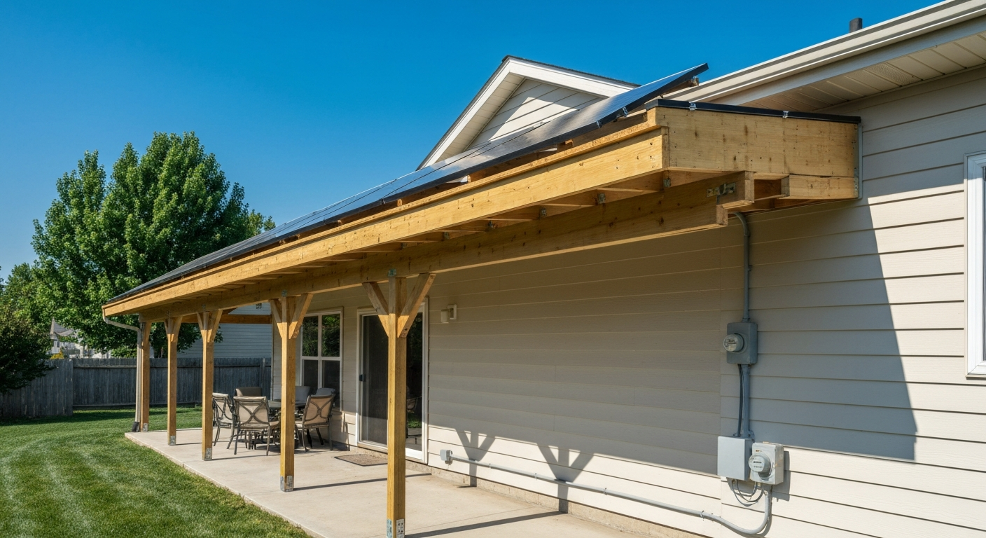
Project overview and who this guide is for
This guide is written for homeowners who are comfortable swinging a framing hammer, reading a tape measure, and following a permit submittal checklist without a general contractor holding their hand. You do not need to be a licensed electrician for every piece of this project, but you will need a licensed electrician to make the final connection to your main panel in most jurisdictions, and you will need to be honest with yourself about that boundary. The structural framing side, the panel mounting, and most of the DC wiring conduit runs are solidly within reach for a competent DIYer. The scope here covers a patio cover in the range of 100 to 400 square feet, attached to a house or free-standing, supporting a 2 kW to 8 kW PV array. What you will walk away with after reading: a site assessment method, a permit checklist, a design choice framework, a materials comparison, structural sizing guidance, and a build sequence you can actually follow.
A few honest constraints up front. First, this is not a plan set. Your local building department will require stamped drawings or at minimum a detailed construction document with beam and footing sizes. Second, if you live somewhere with significant snow loads (more than 25 psf ground snow load) or high wind zones (basic wind speed above 115 mph from ASCE 7 maps), you should hire a structural engineer to review your design before submitting for permit. Third, the electrical side of a grid-tied solar system involves lethal DC voltages (PV strings can reach 300 to 600 VDC) and requires strict adherence to NEC Article 690. Respect those boundaries and this project is very achievable.
Quick decision guide: is a solar panel patio cover right for your home?
Before you commit to the build, run through four quick checks. If you hit a hard stop on any of them, address it before you spend money on materials.
Sun access
Your patio cover roof needs unobstructed sun for at least five to six peak hours per day. Use a free tool like PVWatts or the NREL solar resource map for your address. If your patio faces north or is heavily shaded by a two-story neighbor or large trees, the energy yield may not justify the added cost of PV integration. A south-facing or west-facing patio in a low-shade environment is the sweet spot.
Site and structure
Check your setbacks. Most municipalities require patio covers to sit at least three to five feet from side and rear property lines, and some HOAs restrict height or finish materials. Pull up your local zoning ordinance or call your planning department before you design anything. Also confirm that the wall you plan to attach a ledger to is a wood-framed rim joist or solid masonry wall, not a thin veneer over insulation, which complicates ledger attachment significantly.
Budget
A solar patio cover costs more than a plain shade structure because you are paying for PV panels, racking hardware, inverter(s), wiring, conduit, and often an electrical sub-panel or new breaker. Rough budget ranges: a basic pressure-treated wood lean-to with a 2 kW array runs $8,000 to $11,000 in materials and permits. An aluminum or Alumawood cover with a 4 to 6 kW array runs $13,000 to $22,000. These ranges assume you are supplying the labor. If you hire out electrical and structural work, add $3,000 to $6,000.
Electrical needs
A grid-tied system requires your main service panel to have capacity for a new breaker sized at 125 percent of the inverter's output current rating. A 5 kW inverter at 240V draws about 21 A at full output, so you need a 30 A back-fed breaker and roughly 35 A of available capacity in your panel. If your panel is already full or undersized, factor in a panel upgrade in your budget.
Site assessment and measurements to take
Good measurements at the start save you expensive corrections later. Set aside two to three hours to walk through this assessment before you draw a single line.
- Measure your patio slab or footprint: length, width, and distance from the house wall to the outermost edge. Note any step-downs, drains, or gas line cleanouts inside the footprint.
- Locate your roofline above the patio. Measure from the top of your exterior wall sheathing (where a ledger would attach) down to the finished patio surface. A comfortable finished beam height is 8 to 9 feet above the patio floor; add your rafter depth and panel height above rafter when calculating how much you can pitch the roof before hitting the eave.
- Measure the distance from the ledger attachment point to your main electrical panel or sub-panel, both horizontally and vertically. This determines your conduit run length and wire gauge needs.
- Identify all utility locations: gas meter, electrical meter, any buried lines (call 811 before you dig any footings), and hose bibs. Mark them on your site plan.
- Measure setbacks from all property lines to the proposed post locations. Compare to your local zoning setback requirements.
- Note the slope of existing grade where posts will go. Footings on sloped ground may require stepped depths or a concrete grade beam.
- Check sun angles at summer solstice and winter solstice using a compass app or Solar Pathfinder tool. Document any shading from trees, chimneys, or neighboring structures.
- Photograph the exterior wall at the proposed ledger location and, if accessible, inspect the band/rim joist from inside the crawl space or basement. Confirm it is solid and not rotted.
For the connection points specifically: measure and mark the centerline of each floor joist or roof rafter on the band joist face, because your ledger bolts must land in solid wood. Standard stud/joist layout is 16 inches on center, but verify it, because older homes drift. Also measure the horizontal distance between the proposed post center locations along the beam line, which determines your beam span and drives your beam sizing.
Permits, inspections, and code checklist
This is the step most DIYers want to skip and the step that protects your home's resale value and your homeowner's insurance coverage. A patio cover built without permits can trigger expensive retroactive compliance requirements when you sell. Here is what to prepare.
Documents to prepare for your building permit submittal
- Completed permit application with project description and estimated construction value
- Site plan (plot plan) drawn to scale showing: property lines, existing structures, proposed patio cover footprint, setback dimensions to all property lines, and utility locations
- Construction drawings showing: post sizes and spacing, beam sizes and spans, rafter sizes and spacing, ledger size and fastener pattern, footing dimensions and depth
- Ledger attachment detail: fastener type, diameter, embedment, staggered spacing pattern (IRC/AWC DCA-6 prescriptive tables specify minimum 1/2-inch diameter lag screws or structural screws at tabulated spacing)
- Flashing detail at ledger: show Z-flashing or peel-and-stick membrane lapped over wall WRB and seated under siding
- Footing schedule: diameter, depth below grade (must reach undisturbed soil below frost line), and concrete PSI
- Panel/PV system electrical single-line diagram showing: array layout, module spec sheet, string configuration, inverter make and model, rapid-shutdown device locations (required under NEC 690.12 in most jurisdictions adopting 2017 NEC or later), AC disconnect, conduit routing, and interconnection point at main panel
- Structural calculations or manufacturer's engineering letter if using a pre-manufactured aluminum system such as Alumawood (many jurisdictions, including City of Buckeye AZ, require sealed engineer-stamped plans for these systems)
- Electrical permit application (usually a separate application from the building permit)
Inspection stages to schedule
- Footing inspection: before you pour concrete, call for inspection of the excavated holes at correct depth and diameter
- Framing inspection: after all posts, beams, rafters, and ledger are installed but before any roofing or panel mounting begins
- Ledger and flashing inspection: your inspector will check bolt pattern, flashing laps, and caulk/sealant at penetrations
- Rough electrical inspection: after all conduit, wire pulls, and racking are installed but before you make connections at the inverter and panel
- Final inspection: covers completed structure, panel mounting, all electrical connections, rapid-shutdown label placement, and any required fire department access pathway compliance
One note on fire department access: many jurisdictions now require PV arrays to leave a three-foot clear pathway at the roof ridge and a minimum 18-inch perimeter setback from the roof edge, to allow firefighter ventilation access. On a patio cover this usually means leaving the outer row of panels set back from the cover edge. Confirm these pathway requirements with your local AHJ (Authority Having Jurisdiction) before you finalize your panel layout.
Design options and tradeoffs: lean-to, gable, and free-standing covers
Your three main structural options each have different implications for solar panel tilt angle, structural complexity, and permit requirements. Here is an honest breakdown.
| Design | Solar Tilt Control | Structural Complexity | Best Use Case | Main Drawback |
|---|---|---|---|---|
| Lean-to (attached) | Fixed by pitch from house to outer beam; typically 2:12 to 4:12 pitch | Low to moderate: one ledger, one beam, posts on outer side | Patios directly adjacent to single-story house wall with good southern exposure | Pitch is constrained by house eave height; may limit optimal solar angle in northern climates |
| Gable (attached or free-standing) | Panels go on one or both sloping sides; pitch can be optimized at design stage | Moderate to high: ridge board, two sets of rafters, hip or valley options add complexity | Larger patios where you want more architectural presence and flexible panel placement | More framing, more hardware, longer build time, higher material cost |
| Free-standing | Full pitch freedom; can orient independent of house wall | Moderate: requires footings on all four corners, no ledger needed | Detached patios, pergolas away from house, or where house wall attachment is not feasible | Requires more footings and posts; conduit run to house is longer and more complex |
For most suburban lots, the attached lean-to is the right starting point. It is the simplest to permit, the easiest to frame, and the conduit run to your main panel is short. If your patio faces south or southwest and you can achieve a 15-to-25 degree roof pitch with enough headroom below the eave, a lean-to will deliver excellent PV production. A gable makes sense when you have a larger patio and want symmetry or more headroom at the center. A free-standing structure makes sense when the house wall is not accessible or the patio is more than 20 feet from the main panel room.
Material options: wood, metal, aluminum, and Alumawood
The cover material affects not just cost and appearance but also how you attach PV racking and whether you will need to repaint or refinish the structure over its life. Here is what I have seen work well and what causes headaches.
| Material | Typical Cost (materials only, 200 sq ft) | Lifespan | Solar Racking Compatibility | Maintenance |
|---|---|---|---|---|
| Pressure-treated wood | $1,200 to $2,500 | 20 to 30 years with maintenance | Excellent: standard lag screws or rafter clamps work directly into wood rafters | Repaint or stain every 5 to 7 years; inspect for rot at ledger annually |
| Steel/metal (galvanized or powder-coated) | $2,000 to $4,500 | 30 to 50 years | Good: use metal-specific clamps and self-tapping screws rated for steel framing | Touch up paint on scratches; check for rust at cut ends |
| Extruded aluminum (DIY) | $2,500 to $5,000 | 30 to 40 years | Good: use aluminum-compatible clamps, avoid dissimilar metal contact with steel hardware | Minimal: anodized finishes last well; repaint only if desired |
| Alumawood (pre-engineered system) | $4,000 to $9,000 | 30 to 50 years | Good but requires careful attachment: use manufacturer-approved clamps through slat tops, not through decorative faces | Factory finish holds well; see painting notes below |
Alumawood and painting considerations
Alumawood is a brand of extruded aluminum patio cover system that mimics wood grain finish. It is popular in the Southwest and is structurally engineered by the manufacturer. If you are considering adding solar panels to an Alumawood cover, the key structural question is whether the existing system was engineered to carry PV dead loads (typically 3 to 5 psf for panels and racking). Many jurisdictions, including cities in Arizona, require sealed engineer-stamped plans for Alumawood structures, so you likely already have manufacturer engineering documents on file if it was permitted. For example, the City of Buckeye AZ, Residential Patio Cover Checklist explicitly requires sealed engineer-stamped plans for Alumawood structures blank" rel="noopener noreferrer">City of Buckeye AZ — Residential Patio Cover Checklist. If those plans do not account for PV loads, you will need an engineer's supplemental letter before your solar permit is approved. On the painting side, Alumawood can be repainted with a bonding primer and exterior acrylic paint, but the factory finish is durable enough that most owners never need to do this. If you are building a new Alumawood cover that will host solar panels, specify the panel layout in your permit drawings so post spacing and rafter sizing account for the added load from day one. Can you put solar panels on an Alumawood patio cover? If you want step-by-step construction guidance, see our detailed guide on how to build Alumawood patio covers for practical tips on layout, anchoring, and finishing. Yes, provided the system or supplemental engineer's letter demonstrates the extrusions and post spacing can carry the PV dead and wind loads can you put solar panels on Alumawood patio cover.
Wood is my personal first recommendation for a first-time solar patio cover build because it is forgiving: you can drill anywhere, lag screws are inexpensive and widely available, and if you make a mistake you can sister a new member alongside the old one. Metal and aluminum systems require more precise cutting and the right fasteners for the material, but they will outlast wood with zero rot risk. If you are in a high-humidity climate or near salt air, aluminum or galvanized steel is worth the extra upfront cost.
Structural basics: post spacing, beam sizing, header connections, and framing layouts
I want to be clear that what follows is orientation-level guidance, not a replacement for stamped plans. Use these numbers to have an informed conversation with your building department or engineer, and to sanity-check your design.
Post spacing and sizing
For a wood lean-to cover, 4x4 posts are adequate up to about 8 feet of height with moderate spans. Once your post height exceeds 8 feet or your beam span exceeds 10 feet, step up to 6x6 posts. Common post spacing runs 8 to 12 feet on center along the beam. Tighter spacing (8 feet) means smaller beams; wider spacing (12 feet) requires heavier beams and larger footings. For a solar cover, I lean toward 8-foot post spacing because it gives you more structural redundancy against the added PV dead load and uplift forces.
Beam sizing concepts
A rough sizing rule for a double-ply wood beam (two 2x members nailed together) carrying a 10-foot rafter span at 16 inches on center with standard roof loads: a doubled 2x10 handles about an 8-foot beam span, and a doubled 2x12 handles about a 10-foot span. Add solar panels at 3 to 5 psf dead load, and you should verify against the IRC beam span tables or have an engineer confirm. For steel or aluminum systems, defer to manufacturer span tables, which are load-tested and published by the system manufacturer.
Ledger and header connections
The ledger is the most critical connection in an attached cover. Per IRC and AWC prescriptive guidance, use a minimum 2x8 pressure-treated ledger (ledger depth should match or exceed your rafter depth). Fasteners: 1/2-inch lag screws or structural screws such as LedgerLOK, installed in a staggered two-row pattern at spacing per AWC DCA-6 tables (typically 12 to 16 inches on center staggered). Every ledger needs Z-flashing or peel-and-stick membrane above it, lapped over the wall's weather-resistive barrier and tucked under the siding above. This is not optional; water infiltration behind a ledger is one of the most common and expensive mistakes on attached cover projects.
Common framing layout for a solar lean-to
- Ledger bolted to house band joist at desired finished height minus rafter depth
- Posts set in concrete footings at outer edge, spaced 8 to 10 feet on center along the beam line
- Doubled beam spanning across post tops, notched or bolted with post caps (Simpson LCE or similar)
- Rafters spanning from ledger to beam at 16 or 24 inches on center, with rafter hangers at ledger end and toe-nailed or clipped at beam end
- Purlins (optional, for panel racking) running perpendicular to rafters at spacing matched to panel frame dimensions, or direct-mount rail racking attached to rafter tops
- Lateral bracing: knee braces or diagonal steel strap bracing at corner posts to resist racking from wind
Structural load, wind and snow checks, and when to call an engineer
Patio covers live outside, and code requires them to be designed for the actual site loads: dead load (the weight of the structure and panels), live load (maintenance personnel on the roof, typically 20 psf for roofs not intended for occupancy), wind load, and snow load. These are not guesses; they come from the specific site conditions.
Dead load from PV panels
Most residential PV modules weigh 40 to 50 pounds each, and a 60-cell panel covers roughly 17 to 18 square feet. That works out to about 2.5 to 3 psf for the panels alone. Add racking hardware (another 0.5 to 1.5 psf) and you land at 3 to 5 psf total PV dead load. Your permit submittal needs to document this number. Your structural member sizes need to be confirmed against this combined load.
Wind load
Wind is the most significant structural concern for a patio cover, particularly for uplift. ASCE 7 provides the basic wind speed map by location; most of the continental U.S. interior sits in the 115 to 130 mph exposure B range, but coastal areas, hurricane zones, and tornado-prone regions are significantly higher. At higher wind speeds, uplift forces on a low-slope roof can exceed 40 to 50 psf on the roof edge components and cladding zone. This affects how many lag screws you need in your ledger, how your post bases are anchored, and whether diagonal bracing is required. Look up your address on the ASCE Hazard Tool to get your site-specific basic wind speed before you finalize your design.
Snow load
Ground snow load (pg) varies dramatically by location. In Phoenix, it is essentially zero. In Denver, it is around 30 psf. In parts of New England or the Sierra Nevada, it exceeds 100 psf. Use a ZIP code lookup tool that implements the ASCE 7 ground snow geodatabase to find your pg, then apply the IBC/IRC flat-roof snow load conversion (typically 0.7 times pg for a standard exposure condition). A flat or low-slope patio cover in a 30 psf snow zone needs beams and rafters sized for that load plus dead load, which often means stepping up one or two lumber sizes compared to a no-snow climate.
When to hire a structural engineer
Be honest with yourself about the following thresholds. If any of these apply to your project, budget for a structural engineer review before you submit for permit. An engineer's letter typically costs $400 to $1,200 and will save you from a costly redesign mid-build.
- Ground snow load at your site exceeds 25 psf
- Basic wind speed at your site exceeds 115 mph (ASCE 7 map)
- Your cover span (rafter length or beam span) exceeds 12 feet
- You are using a pre-manufactured aluminum system such as Alumawood and need to add PV load not covered in the original manufacturer engineering
- Your ledger attaches to something other than a standard wood-framed band joist (masonry, structural insulated panel, or ICF walls)
- Your building department explicitly requires sealed plans (common in AZ, FL, TX, and other high-wind states)
- Your cover is free-standing with post heights exceeding 10 feet
- You are in a seismic zone with a design spectral acceleration (Ss) above 1.0g
The goal is not to scare you off the project; it is to make sure the structure you build stays standing in the first real windstorm. A structural engineer on a project like this is a one-time cost that pays for itself in confidence and permitting speed.
Solar panel mounting: racking, attachment methods, and wiring basics
Once your structural cover is framed and inspected, the PV mounting side of the project begins. There are two broad mounting strategies for a patio cover: flush rail racking directly on rafters, or a ballasted or clamp-based system on purlins. For a DIY build, rail racking is the cleaner choice.
Rail racking on wood rafters
Rail racking systems (IronRidge, Unirac, and similar brands) consist of aluminum rails that run parallel to the rafters or perpendicular to them, mounted to the rafter tops with lag screws through a flashing foot. The rails span between mounting feet, and the panel frames clamp to the rail with mid-clamps (between panels) and end-clamps (at the array perimeter). Mounting foot spacing follows the manufacturer's span tables based on your design wind speed and rail type. A common starting point is one mounting foot every 48 to 60 inches along each rail, but confirm this with the racking manufacturer's layout tool. Each lag screw into a rafter must penetrate at least 2.5 inches into solid wood after passing through the foot and any roofing material. Since you are building the cover new, you can design the rafter spacing to align perfectly with the panel frame dimensions, which simplifies the layout significantly.
Attachment to metal and aluminum covers
If you are mounting on an aluminum or metal cover, use aluminum-to-aluminum clamps or stainless steel hardware to avoid galvanic corrosion. Self-tapping stainless steel screws into structural aluminum extrusions are a common solution. For Alumawood systems specifically, the preferred approach is to mount rails through the top surface of the structural beam channels (not through the decorative wood-grain slats), using the manufacturer's approved attachment hardware. Confirm the attachment method with the racking manufacturer before you order.
Wiring, inverters, and rapid shutdown
Micro-inverters (one per panel, such as Enphase IQ series) are the most DIY-friendly choice for patio covers because each panel is independently converted to AC, the DC voltage at any point never exceeds a single panel's voltage (typically 30 to 60 VDC), and rapid-shutdown compliance (NEC 690.12) is built into the system without separate shutdown modules. String inverters (one inverter for the whole array, brands like SolarEdge or Fronius) are more efficient at scale but run high DC string voltages and require separate module-level rapid-shutdown devices on roof-mounted arrays under the 2017 NEC and later. Budget for the rapid-shutdown devices if you go the string inverter route. All wiring runs on a patio cover should be in conduit: PVC conduit is acceptable for roof runs but use metal conduit (EMT or rigid) where exposed to physical damage. The conduit run from the array to the inverter, and from the inverter to the main panel, needs to be sized for the wire gauge required for your inverter output current.
Step-by-step build sequence
- Pull both permits (structural and electrical). Do not start digging until permits are in hand.
- Mark and excavate footing holes. Typical residential patio cover footing: 12-inch diameter, 18 to 24 inches deep below grade in no-frost areas, below frost depth in freeze-thaw climates. Call 811 at least 48 hours before digging.
- Set post bases or pour concrete with embedded post anchors (Simpson ABA or similar). Let concrete cure 48 hours minimum before loading.
- Cut and set posts to height. Brace plumb with temporary 2x4 kickers.
- Attach ledger to house wall. Apply Z-flashing or peel-and-stick membrane first, then fasten ledger with 1/2-inch lag screws in staggered pattern per AWC tables. Call for ledger/framing inspection if your jurisdiction stages inspections here.
- Set beam on post tops using post caps. Check level across full beam length.
- Install rafters from ledger to beam with rafter hangers at ledger and rafter ties or clips at beam. Check that all hangers are fully nailed.
- Install any blocking, knee braces, or lateral strapping per your plans.
- Call for framing inspection. Do not proceed until inspection is passed.
- Install racking mounting feet on rafter tops with lag screws. Flash each foot with butyl tape or manufacturer-supplied flashing kit.
- Run conduit from array location down to inverter location and from inverter to main panel. Pull wire through conduit but leave disconnected at both ends.
- Mount rails on mounting feet, torque to manufacturer spec.
- Install rapid-shutdown devices or module-level electronics (micro-inverter trunking cables for Enphase, SolarEdge optimizers if using string inverter).
- Slide panels into rails and install mid-clamps and end-clamps. Torque per manufacturer spec (typically 10 to 20 ft-lbs).
- Make DC wiring connections at module level, install combiner or trunk cable connections, ensure all DC connectors are fully seated and locked.
- Call for rough electrical inspection.
- After rough electrical passes, make final connections at inverter and at main panel breaker. Have a licensed electrician make the main panel connection if required by your jurisdiction.
- Attach all required labels: rapid-shutdown label at inverter and at main panel, AC disconnect label, PV system label at utility meter.
- Call for final inspection. Have your inverter spec sheet, racking layout drawing, and electrical single-line diagram on site.
- Commission the system per inverter manufacturer instructions and verify production output matches expected PVWatts estimate within 10 to 15 percent.
Tools you will need
- Circular saw or miter saw for framing lumber cuts
- Drill with 1/2-inch spade bit or auger bit for ledger lag screw pilot holes
- Impact driver for driving lag screws and structural screws
- Post hole digger or rented power auger for footings
- 4-foot and 2-foot levels, plus a long string line for leveling the beam across multiple posts
- Chalk line for marking rafter layout
- Tape measure (25-foot minimum) and framing square
- Conduit bender and conduit cutter for electrical runs
- Wire stripper, lineman's pliers, and non-contact voltage tester
- Torque wrench or calibrated impact driver for racking hardware
- Safety harness and roof anchor if working at roof pitch above a slab
- Safety glasses, work gloves, and hearing protection throughout
Common mistakes and how to avoid them
- Skipping the ledger flashing: this is the single most common mistake on attached cover projects and leads to rot inside your wall framing within three to five years. Flash before you fasten, every time.
- Undersizing footings for the post count: each post concentrates load into a small area of soil. If your footing is too small in diameter or does not reach undisturbed soil, it will settle under combined structure and panel weight.
- Not accounting for panel tilt in rafter pitch: panels produce less energy on a near-flat surface and shed rain and debris poorly. Aim for at least a 5-degree tilt (approximately a 1:12 roof pitch) even if aesthetics push you toward flat.
- Using steel hardware in contact with aluminum racking: galvanic corrosion between dissimilar metals will eat through connections within a few years. Use stainless steel or aluminum hardware at all aluminum contact points.
- Forgetting to derate wire for conduit temperature: wire inside conduit in full sun on a dark roof can reach 140 to 160 degrees F, which requires wire ampacity derating. Check NEC Table 310.15(B)(2)(a) and use the appropriate derating factor for your conduit temperature and wire count.
- Connecting PV system to an already full main panel without verifying backfeed breaker capacity: the 120 percent rule in NEC 705.12 limits total breaker ampacity to 120 percent of panel bus rating. If your 200A panel is full, you may need a breaker replaced or a new sub-panel.
- Omitting required labels: inspectors fail final inspection for missing rapid-shutdown labels, AC disconnect labeling, and PV system warning signs more often than for any structural issue.
Finishing, painting, and long-term maintenance
For a wood cover, apply a UV-blocking exterior paint or solid stain within 30 days of framing completion to prevent checking and graying. For step-by-step instructions on prepping and painting, see how to paint a patio cover. Use a primer coat rated for pressure-treated lumber (standard latex primer can fail to bond to PT chemicals; use an oil-based primer or a primer specifically rated for PT wood). Re-coat every five to seven years, and inspect the ledger-to-wall junction annually for any signs of water entry or wood softening.
For aluminum and Alumawood covers, the factory finish is durable and typically requires no painting. If you want to change the color later, prep with a scuff sanding and an adhesion-promoting bonding primer before applying exterior acrylic topcoat. This is straightforward on bare aluminum extrusions; just make sure the paint system is rated for metal exteriors and that you mask off any panel mounting hardware and wiring access points before you spray.
On the solar side, clean your panels two to four times per year depending on dust and pollen load in your area. Use a soft brush and water; avoid pressure washers directly on connectors or wire runs. Inspect all conduit and wire entry seals annually for cracking. Check racking torque values on a representative sample of clamps every two years; thermal cycling loosens hardware over time. Monitor your inverter's production data dashboard monthly and investigate any string or panel showing more than 10 percent lower output than its peers, which usually signals a shade issue, a faulty optimizer, or a loose connector.
When to hire a pro instead of going it alone
You do not have to hand over the whole project. The most common and sensible hybrid approach is to handle the structural framing and panel mounting yourself, and hire a licensed electrician for the final panel connection and any work inside the main service panel. That typically costs $500 to $1,500 for a half-day's work and keeps the rest of the project in your hands. Hire a structural engineer when you hit any of the load or span thresholds listed in the structural section above. Hire a full solar contractor if your roof pitch, high DC voltage string wiring, or local code complexity feels beyond your current skill level. There is no shame in scoping your own involvement honestly; a partially DIY solar cover that is safe and permitted is far better than a fully DIY one that fails inspection or causes a roof leak.
FAQ
What permits and documentation will I likely need before building a solar-panel patio cover?
Most U.S. jurisdictions require a building permit for attached or freestanding patio covers with solar panels. Typical submittal items: completed permit application, site/plot plan showing property lines/setbacks and array location, construction details (post/beam/rafter/ledger sizes and spans), footing sizes and reinforcement, ledger attachment details and flashing, roof/panel dead load and framing capacity, electrical single-line diagram and NEC compliance (Article 690), inverter/location and disconnects, and inspection staging (footing, framing/ledger, electrical, final). Larger spans, Alumawood systems, or increased loads often require engineer‑stamped structural plans—verify local AHJ checklist early.
How do I determine if my existing patio cover framing can support PV panels?
Start with the basics: calculate added dead load (panels + racking ≈ 3–5 psf). Compare to framing capacity using prescriptive tables (IRC/AWC) or manufacturer span tables. Key checks: beam/post sizes and spacing, joist/rafter spans and deflection limits (L/240 for roof live load or per local code), footing sizes and soil bearing capacity, and connection detail capacity (ledger bolts/structural screws). If your added load, wind uplift, or snow loads push any member beyond code tables or the ledger/ledger flashing detail is unverified, consult a licensed structural engineer and include site wind/snow values (ASCE 7) or local design maps.
When do I need an engineer‑stamped plan?
Require an engineer when: you’re modifying or relying on an existing structure without known capacity; spans/loads exceed prescriptive code tables; using premanufactured systems that local code requires sealed plans (common for Alumawood); site-specific high wind/snow zones or complex load paths; or your municipal checklist specifically requests sealed calculations. If unsure, ask your building department before buying materials.
What are the common patio cover designs for mounting solar panels and pros/cons of each?
Lean‑to (attached sloped to house): easiest for wiring and permits; requires correct ledger and flashing; limited tilt options. Gable (peaked attached): better ventilation and tilt control; more complex framing/ledger. Free‑standing (separate pergola/carport): flexible siting and orientation; needs independent footings and larger structural members; may avoid house attachment permitting complexities. Consider roof pitch for optimal panel tilt, shading, and access for maintenance.
Which framing/material options are best: wood, metal, or aluminum/Alumawood?
Wood (pressure‑treated or cedar): economical, easy to modify, but requires maintenance and corrosion‑resistant fasteners; heavier so may need larger foundations. Steel/metal: high strength, smaller profiles, durable, may need special tools/welds and corrosion protection. Aluminum/Alumawood: lightweight, low maintenance, often sold as kits—good appearance but many AHJs require engineer‑stamped plans for spans; attachment details differ and painting requires specific primers. Choose based on budget, local code acceptance, desired lifespan, and compatibility with mounting rails.
How should I attach PV mounting rails to different patio cover materials?
Wood rafters/beams: attach rails with lag bolts or structural screws per manufacturer spacing (typically 4–8 ft along rail) into rafter or blocking; ensure 1.5–2" minimum embedment for lag/through bolts or use structural rated ledger screws. Metal purlins/steel beams: use manufacturer-supplied clamps or self‑tapping TEK screws into predrilled holes with neoprene washers; weld plates only if done by qualified welder. Aluminum/Alumawood: follow kit manufacturer instructions—often using through-bolts into engineered fastening points or rail clamp systems. Always use stainless or hot-dip galvanized hardware near pressure‑treated wood and follow torque and spacing per racking and fastener manufacturer.